Ce dont vous avez besoin
-
Cette étape n’est pas traduite. Aidez à la traduire
-
There are two PH0 Screws in the socket which hold the cable.
-
Unscrew two PH0 Screws and pull off the cable holder.
-
-
Cette étape n’est pas traduite. Aidez à la traduire
-
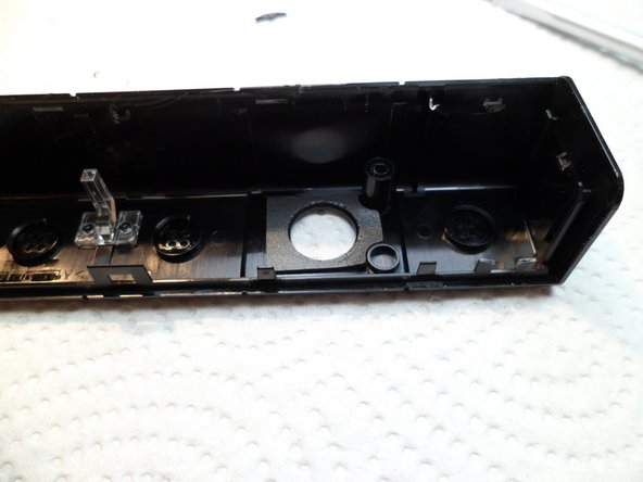
The next two PH0 Screws are located BEHIND the two polycarbonate-plates of the two camera-lenses. Take a sharp tweezer and stab under that plate. The plates are glued with a sticky tape to the housing. These plates are very fragile and will break if handled incautious.
-
-
Cette étape n’est pas traduite. Aidez à la traduire
-
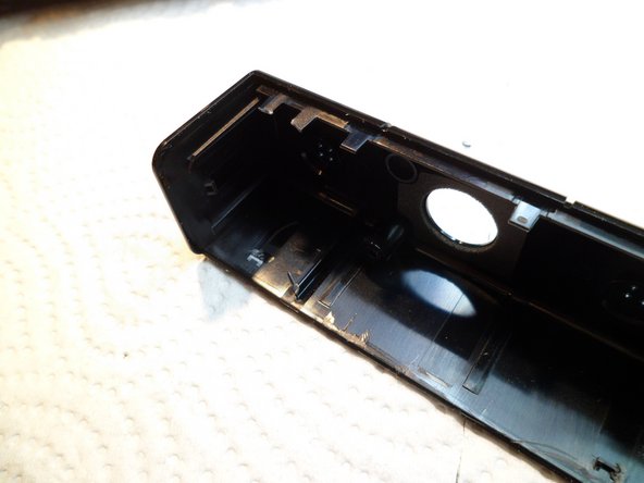
There is one more PH0 screw to remove. This one is behind the other lens.
-
This was the easy part.
-
-
-
Cette étape n’est pas traduite. Aidez à la traduire
-
Encore two photos where to locate these nasty clips
-
-
Cette étape n’est pas traduite. Aidez à la traduire
-
The other half of the housing is attached to a solid U-Frame with the electronics.
-
There are four silver screws, PH0.
-
Four microphones, two with black/yellow cables and two with black/red wiring.
-
-
Cette étape n’est pas traduite. Aidez à la traduire
-
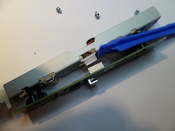
The backside of the U-frame. The cable is not soldered, there is a plug.
-
Detail of the plug.
-
-
Cette étape n’est pas traduite. Aidez à la traduire
-
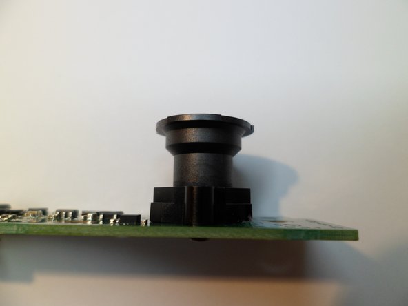
The lenses, plastic, glued tight.
-
NOT ADJUSTABLE.
-
-
Cette étape n’est pas traduite. Aidez à la traduire
-
Backside, two small PH0 at each CCD. But the Cameramodules are clued to the board,too - without destruction, you can not open it.
-
I want to save it as spare-part, so i don't want to open it. So here is finito capito. :) Thanks for watching...
-
-
Cette étape n’est pas traduite. Aidez à la traduire
-
Extra: The wiring.
-
It's an USB3 cable without green/white Pimf. There are three SEPARATE ISOLATED metalfoil shields with wire, red-black-power and two Pimf yellow/blue and orange/green. So ja, thats it. Paulaner.
-


7 commentaires
Only 7 steps? Where is the rest of the teardown? I wanted to see detailed images of the optics.
Ja, okay, i made some pictures for you. The optics are in Step 10.
Enjoy.
Freundliche Grüsse. :)
Does anyone think it would be possible to cut the wires from two cameras and splice the wires together and put the power on a A/B rocker switch to switch between two cameras?