Cette version peut contenir des modifications incorrectes. Passez au dernier aperçu vérifié.
Ce dont vous avez besoin
-
Cette étape n’est pas traduite. Aidez à la traduire
-
Remove all the cables, including the power cables before opening the unit.
-
-
Cette étape n’est pas traduite. Aidez à la traduire
-
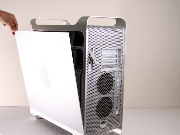
Remove the air deflector (the clear plastic cover) by pulling on the handle.
-
-
-
Cette étape n’est pas traduite. Aidez à la traduire
-
The cooling fan unit is located on the bottom right of the Apple G5 Desktop.
-
-
Cette étape n’est pas traduite. Aidez à la traduire
-
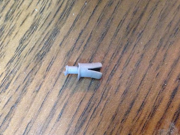
Remove the G5 metal cover from the processing/cooling unit of the computer. NOTE: Apple inserted a rather fragile plastic pin that inserts through the top divider shield and clips into a tab on the hidden ledge of this CPU shield. Removing this pin, certainly voided Mac's warranty - but more appropriate for now, voids most after-market insurance plans. A replacement pin (new) is hard to get ahold of, and very few are talented and patient enough to remove this pin without damaging it. Just something to keep in mind. If you have no warranty any longer or don't care, please continue...
-
Pull the metal plate to the left and outward to remove the plate from the processing/cooling unit.
-
-
Cette étape n’est pas traduite. Aidez à la traduire
-
Unplug the fan's power cable from the upper rightmost corner of the motherboard (connection J45). If there is a video card in place, carefully pull the cable plug down between the back edge of the video card and the motherboard. Note, the photo shows the unplugged cable and the area it plugs into outlined in yellow. No video card is shown in this photo.
-
-
Cette étape n’est pas traduite. Aidez à la traduire
-
Locate the tabs on the fan unit.
-
While pushing in on the tabs, highlighted in yellow, pull the fan back towards the cooling unit.
-
-
Cette étape n’est pas traduite. Aidez à la traduire
-
After removal of the bottom right fan the space should look like this.
-


Annulation : je n'ai pas terminé ce tutoriel.
33 autres ont terminé cette réparation.
Équipe

Cal Poly, Team 5-8, Forte Winter 2010 Membre de l'équipe Cal Poly, Team 5-8, Forte Winter 2010
CPSU-FORTE-W10S5G8
7 membres
20 tutoriels rédigés