Cette version peut contenir des modifications incorrectes. Passez au dernier aperçu vérifié.
Ce dont vous avez besoin
-
Cette étape n’est pas traduite. Aidez à la traduire
-
Use the blunt end of the spudger to pry the adhesive rubber pads from the top left and right edges.
-
-
Cette étape n’est pas traduite. Aidez à la traduire
-
Use a Phillips #0 screwdriver to remove two 6.7 mm screws.
-
-
Cette étape n’est pas traduite. Aidez à la traduire
-
Use your fingers to identify the location of the screw under the bottom label.
-
-
Cette étape n’est pas traduite. Aidez à la traduire
-
Use a Phillips #0 screwdriver to remove one 6.7 mm screw.
-
-
-
Cette étape n’est pas traduite. Aidez à la traduire
-
Turn the mouse over so the bottom is facing down.
-
Separate the top casing from the bottom base by pulling the top casing upwards.
-
-
Cette étape n’est pas traduite. Aidez à la traduire
-
Disconnect the ribbon connector between the motherboard and the LED lights by pulling upward.
-
-
Cette étape n’est pas traduite. Aidez à la traduire
-
Disconnect the ribbon connector between the motherboard and the USB cable by pulling upward.
-
-
Cette étape n’est pas traduite. Aidez à la traduire
-
Use a Phillips #0 screwdriver to remove three 5.5 mm screws.
-
-
Cette étape n’est pas traduite. Aidez à la traduire
-
Use a Phillips #0 screwdriver to remove two 11.5 mm screws on the side buttons.
-
-
Cette étape n’est pas traduite. Aidez à la traduire
-
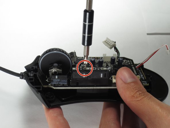
Use a Phillips #000 screwdriver to remove one 5.0 mm screw.
-
-
Cette étape n’est pas traduite. Aidez à la traduire
-
Disconnect the ribbon connector between the motherboard and the optical sensor.
-
-
Cette étape n’est pas traduite. Aidez à la traduire
-
Remove the motherboard by grasping the sides and gently pulling upward.
-


Annulation : je n'ai pas terminé ce tutoriel.
5 autres ont terminé cette réparation.
Équipe

Baylor, Team S5-G2, Williams Spring 2017 Membre de l'équipe Baylor, Team S5-G2, Williams Spring 2017
BU-WILLIAMS-S17S5G2
3 membres
6 tutoriels rédigés