Introduction
Suivez les étapes de ce tutoriel pour retirer, transférer et/ou remplacer l'ensemble haut-parleur interne et capteurs avant de votre iPhone XR. Cet ensemble inclut le haut-parleur interne, le microphone, le capteur de luminosité ambiante, l'illuminateur infrarouge et le capteur de proximité.
Chaque ensemble est couplé en usine avec son iPhone, vous devez donc le transférer depuis votre ancien écran sur le nouveau à chaque remplacement d'écran.
L'illuminateur infrarouge fait partie du système de reconnaissance biométrique Face ID. Celui-ci ne fonctionnera plus si le composant d'origine est abîmé ou mal installé. En le remplaçant avec une nouvelle pièce, vous perdrez la fonction Face ID. Faites très attention en effectuant une réparation à ne pas endommager ces composants. En tel cas, seul Apple pourra restaurer la fonction Face ID.
Ce dont vous avez besoin
-
-
Éteignez votre iPhone avant de commencer le démontage.
-
Dévissez les deux vis Pentalobe de 6,7 mm au bord inférieur de l'iPhone.
-
Juste en dessous de chaque vis Pentalobe se trouve un joint noir. Pour une protection maximale contre les liquides et la poussière, vérifiez l'état des joints ou remplacez les vis lors du remontage.
-
-
-
Recouvrez l'écran de bandes de ruban adhésif, qui se chevauchent, jusqu'à ce que toute la surface soit couverte.
-
Si la ventouse n'adhère pas au cours des étapes suivantes, pliez un morceau de ruban adhésif épais (du ruban adhésif toilé p.e.) pour former une poignée et soulevez l'écran de cette façon.
-
-
-
Tirez la poignée bleue vers l'arrière pour débloquer les bras de l'Anti-Clamp.
-
Insérez le côté droit ou gauche de votre iPhone entre les bras.
-
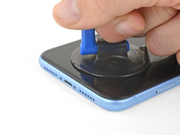
Positionnez les ventouses en bas de l’iPhone. Une à l'avant et l'autre à l'arrière.
-
Appuyez sur les ventouses afin d'appliquer la pression à l'endroit désiré.
-
-
-
Tirez la poignée bleue vers l'avant pour bloquer les bras.
-
Tournez la poignée dans le sens horaire, de 360 degrés ou jusqu'à ce que les ventouses commencent à s'étirer.
-
Vérifiez que les ventouses restent bien alignées entre elles. Si elles commencent à se décaler, détachez-les pour les réaligner.
-
-
-
Chauffez un iOpener et faites-le passer à travers les bras de l'Anti-Clamp.
-
Pliez l'iOpener de façon qu'il repose sur le bord inférieur de l'iPhone.
-
Attendez une minute que l'adhésif se ramollisse et qu'un espace s'ouvre.
-
Insérez un médiator sous l'écran et le joint en plastique, et non dans l'écran.
-
Passez les trois étapes suivantes.
Please UPDATE THIS STEP to say 'insert the opening pick underneath the PLASTIC FRAME OF THE SCREEN' and not the screen. Way too many people are taking this as the way to do it then posting their screen looks different when it's open when they've actually removed the screen leaving the frame in place. It's not rocket science.
Thanks for the suggestion! We updated this step to clarify that.
-
-
-
Prenez un sèche-cheveux ou un pistolet à air chaud, ou bien préparez un iOpener et posez-le en bas de l'iPhone pendant environ une minute afin de ramollir l'adhésif qui se trouve en dessous.
An alternative to the Iopener or heat gun is to heat water to EXACTLY 80 degrees F (cooking thermometer is great for this) and pour into a reinforced ziplock type bag. Leave the bag on the screen, but be sure that none of the hot water rests on the zipper portion, as the water is hot enough to soften that seal and leak out on to your device! This meat had is my personal favorite as the heat is distributed very equally and precisely as compared to a heat gun, but is more accessible than the Iopener.
-
-
-
Tirez sur la ventouse de façon ferme et constante pour ouvrir un léger interstice entre le panneau frontal et la coque arrière.
-
Insérez un médiator dans l'interstice sous l'écran et le joint en plastique, pas dans l'écran lui-même.
-
-
-
Faites glisser le médiator le long du coin inférieur gauche de l'iPhone pour trancher l'adhésif qui maintient l'écran en place.
I think it's important to note that depending on how a screen was damaged, make sure to insert the pic under the black bezel directly under the actual screen. This bezel is a frame around the digitizer. I unknowingly inserted the pic between the bezel and the screen, and separated them both. I did this all the way around the phone. So I basically had to struggle to keep together two different sections of the display assembly because of this mishap, until I removed all the ribbon connectors. It made things much more difficult.
-
-
-
Réinsérez votre médiator dans le bord inférieur de l'iPhone et faites-le glisser vers le côté droit pour continuer à faire céder l'adhésif.
My replacement screen for the XR has a black rim but it looks pink. Is that normal?
Step 11 says not to insert your pick around the right side to avoid damaging cables, then Step 12 says to insert it on the right side. Help, I'm confused!
Hi there!
Thank you for the feedback! The wording in step 11 was definitely ambiguous, so we have changed it! You only need to avoid the marked spots rather than the right edge.
-
-
-
-
Ouvrez l'Phone en faisant pivoter l'écran vers la droite, comme la couverture arrière d'un livre.
-
Posez l'écran iPhone contre un objet pour qu'il soit maintenu à la verticale pendant que vous poursuivez votre réparation iPhone XR.
sure looks like the "hinge" is on the right hand side to me.. not left...!
If you leave the suction cup attached to the screen during the “hinging” process, it makes for a very handy holder for the screen until it’s completely detached.
-
-
-
Dévissez les trois vis Y000 de 1,2 mm qui fixent le cache du connecteur de la batterie.
-
Ôtez le cache.
Definitely make sure all three lobes of your tool are aligned before use (it’s a little harder to tell with this style of bit) and apply even and adequate pressure to ensure it grabs as you spin the driver to prevent disfiguring the lobes/slot of the screw head.
Unfortunately my Y000 tool was perhaps not the best fit (tolerance a bit off) in these screws and I ended up stripping out the heads of all three of these. I started to panic but after I sanded the tip of my Y000 bit down a little with super fine grit (1000CW-C) sand paper to flatten the domed tip (visible with macro lens) and give it a bit more bite I was able to remove and reinstall without issue—in fact I had to remove and install them twice since I forgot my adhesive tape during reassembly, so the screws survived and the sanded bit worked.
+1 to above comment. I bought a cheap kit from Amazon and the Y000 screw driver is not good for this job. I’m concerned that I may have disfigured the heads and i type this comment in the midst of my fix :D Be gentle and assess if you can remove at least one screw with your driver before rummaging through all three and other similar screws holding display connector as well.
Update to above comment. I got hold of a Y0.8 screw driver bit (lucky to find an ORIA screw driver kit in my office) and it works like wonders :) Now back to work…
-
-
-
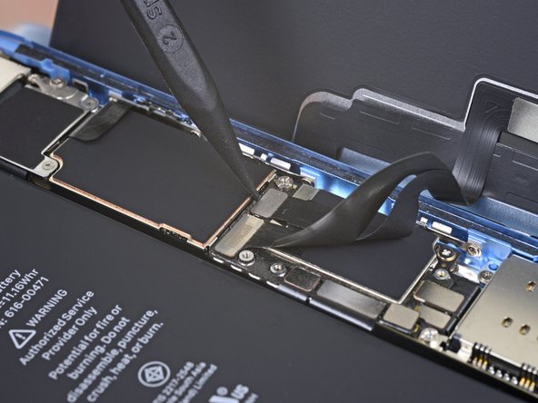
Faites levier avec la pointe d'une spatule (spudger) pour soulever le connecteur tout droit hors de sa prise.
-
Écartez légèrement le connecteur de la carte mère pour l'empêcher de faire accidentellement contact avec la prise et d'alimenter le téléphone pendant que vous effectuez votre réparation.
-
-
-
Dévissez les deux vis Y000 de 1,2 mm qui fixent le cache du connecteur de l'écran.
-
Enlevez le cache.
-
-
-
Prenez la pointe d'une spatule pour soulever et déconnecter la nappe de la vitre tactile.
-
-
-
Prenez la pointe d'une spatule pour débrancher le connecteur de la nappe de l'écran.
The new display cable isn’t snapping in but I was just able to snap in the old one. Did I break the new one somehow?
Same it is really frustrating, just keeps slipping up and its bound to get damaged
-
-
-
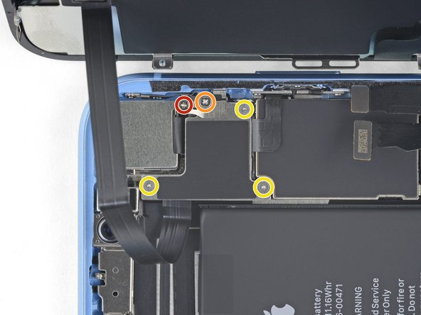
Dévissez les cinq vis qui fixent le cache du connecteur de la carte mère à la coque arrière :
-
Une vis cruciforme #000 de 1,3 mm
-
Une vis cruciforme #000 de 1,5 mm
-
Trois vis Y000 de 1,2 mm
-
Retirez le cache.
I’m not sure it makes much if any difference, but we went ahead and swapped the order for you guys. Thanks for your comments!
I just repaired another XR, and you are right! It doesn’t make any differnerce in the order these screws come out. I still damaged this fragile piece. As I work on more of these, I’ll figure out a way to remove this screw without damaging the clip. For now everyone, just use extra caution when removing the 1.3mm phillips screw! Thanks Jeff
I’ve now done at least 6 of these so far and I have fairly consistent good results by taking the 2 Philips head screws out first, then doing the Y screws.
Stow -
Is this piece important for the repair if broken? I have broken it on a home repair. What is it used for? Is it a grounding connection or is it completely unimportant. More information needed please
I’m wondering that too. Is this piece important?
I can confirm that taking out the 1.3 mm screw first then the 1.5 mm screw works the best. If done correctly, you should be able to to remove the rest of the screws and pull the panel off with the clip still attached to the panel. For reassembly, start with the 1.5 mm screw then the 1.3 mm screw.
I don’t remove the small screw at all. I just slide out the metal cover plate and slide back in to reassemble.
this is what i have done as well. Care is still needed to avoid damaging this part. However, it is seemingly far less prone to damage or loss and thus less risky for this repair process.
I too broke this shield. In looking over this problem I believe it’s best to loosen, but not remove, either screw first then the other. To be clear, loosen the red or yellow screw but only just to break it free, then the second screw. Then remove both and the others and the shield should remain in one piece. I put it back with the broken part (on the red screw) and made sure the two are in contact so there’s conductivity as these shields serve a purpose other than just holding in connectors. My phone works fine with this fix.
Is this small bracket important if broken??
Mine is broken
Mine is broken and my apple pay doesn’t work. Something to do with NFC antenna this little clip??
I'm guessing so. I replaced a screen on a phone I bought from a friend. I noticed this bracket was broken when I disassembled the phone but didn't think much of it. When I reassembled it my NFC also does not work. Bummer. A lot of people in these comments have asked if it is crucial that this bracket be connected. Can someone from iFixit or other please reply to those comments?
Kyaw-Zin is right because the shield contains of two tin parts. But there is another option:
1. Unscrew the yellow and orange screws first.
2. Lift the shield gently that it can turn about 20° anticlockwise.
3. Open the red screw and let the shield turn with it the first degrees.
The first time I did this repair, I didn’t see the comments ahead of time and broke the bracket, even removing the 1.3mm screws first. The second time I did the repair, I was prepared and being extra careful, but the simple act of turning the 1.3mm screw head was enough to break it. If I ever have to do this repair again, I’ll just leave the screw in and try to slide the plate out with the screw (and bracket, hopefully) still in tact, as per Kyaw-Zin Win.
None of the screw driver bits I got fits the 1.3mm and 1.5mm screws. How do I remove them?
Same issue as above. The bits provided in the kit do not work with the 1.3mm and 1.5mm screws
Further to above comment about bit not working. Had to go and purchase another PH000 from Home Depot and that worked
I’ve broken that little bracket attached to the red screw. Is it important and can I get a replacement????? Thanks all
Broken the clip. Is this important??
Don't remove the 1.3 Phillips screw! Twisting this screw will break the smaller bracket that is clipped to the larger. Remove all the other screws. Block the smaller bracket from moving as you gently slide the larger bracket horizontally toward the battery until free. The smaller bracket can stay in place while the screen is replaced. When reassembling, support the small bracket by backing with a spudger or similar tool.
I just broke the smaller bracket also :( I didn´t notice these comments until now :(
It looks like part of the antenna for NFC, as all except NFC works on my iPhone now.
It should be repairable using some wire wrap wire, either twisted around the two screws that connected that part of the bracket (or soldered in place). I will try and report back if it works.
Success!! I managed to re-construct the small arm of the bracket by screwing the 1.3mm screw back in with some 0.3mm enamel wire soldered into what was left of the small bracket arm on the screw, then the other end of the enamel wire I wrapped under the 1.5 wire screw's head (enamel exposed to bare metal), then screwed both screws down. also I lifted up the small metal arm with a screw driver (to make sure it reconnects with the display grounding square) ..and NFC worked again (slightly different antenna pattern mind (need to place cards slightly higher up the rear of the phone). Anyway works again :)
-
-
-
Avec la pointe de la spatule, soulevez le connecteur de l'ensemble capteurs avant hors de sa prise.
During testing, make sure your proximity sensor is not on upside down, as it’s easy to connect upside down. Your phone will boot loop if it’s on incorrectly.
-
-
-
Ôtez l'ensemble écran.
unclear if this is where screen removal ends
I had the same question, but the answer is yes. Steps 21-30 are removing parts from the original screen that need to be reattached onto the new screen. You are no longer working inside the frame, but on the back of the screen itself.
I apologize for missing these comments initially, but yes that’s correct, the screen is removed now and the rest of the guide goes on to other parts, either in the phone or on the back of the screen. Good luck with the repair!
The alternate method of removing the battery should be highlighted as a standard option. There is so much more work and potential to damage the parts than if you left them in place and carefully with plenty of heat remove the battery. I so wish I had seen this before!
-
-
-
Dévissez les quatre vis qui fixent l'ensemble haut-parleur/capteurs à l'arrière de l'écran :
-
Deux vis cruciformes de 1,6 mm
-
Une vis cruciforme de 2,3 mm
-
Une vis Y00 de 1,2 mm
Do you really need to do step 21-30, because it says to replace, do it in reverse. Which means you are taking the components off and putting them back on without touching the screen? sorry if this is a dumb question, i’ve never done this before.
Good question! It depends on which guide you are completing. If you are replacing the screen, you do need to complete steps 21-30, in order to remove the front assembly and transfer it to your replacement screen. The front assembly contains the Face ID hardware, which is biometrically linked to the logic board.
Now, if you are completing other guides, you may not need to remove the front assembly. Guides should have the steps slotted in only if they are pertinent to the procedure.
I had the same question, but the answer is yes. Steps 21-30 are removing parts from the original screen that need to be reattached onto the new screen. You are no longer working inside the frame, but on the back of the screen itself.
Im reassembling and notice there are no threaded screw holes to secure the speaker/sensor assembly on the new display. no way to secure it at all. Do i not need to secure it?
Hi Ashley,
There should definitely be screw holes to secure the assembly to the new display. If you purchased the part from iFixit, please contact our customer support, and we will sort things out for you!
Please contact our customer support and we will get the issue resolved!
-
-
-
Avec une pincette, repliez délicatement l'ensemble haut-parleur pour l'éloigner du bord supérieur de l'écran.
I don’t understand. It clearly appears that one should stop disassembling after this step. Peeling off the tape here should provide access to the solder connections. Why remove a bunch of other adhered parts? ESD concerns?
Of course, taking care not to transmit heat to the screen assembly below would be prudent. But it’s unlikely much if any heat would conduct even without using any sort of insulating spacer, assuming one’s soldering technique is acceptable. With a thermal mass that small, overheating the connection is the big concern. Especially since it is lead-free solder.
(It has a high melting point. If you didn’t already know that, this is definitely not the best project to develop your soldering skills! You can still do it, but should def practice on similar connections until you feel proficient. Lifting a pad or overheating a nearby component are both dangers. Yet, the cost of the part is low enough you could buy two (just in case) and still come out ahead of Apple’s fee. Use flux or you’ll struggle!)
Hey Ryan,
You are right in that after this step, you could de-solder and replace the earpiece individually, if you choose to do some careful de-soldering and soldering. Alas, not everyone has the background and skill to do so! By instructing users to replace the complete assembly, we bypass the need to solder, and allow a wider audience to successfully complete the repair.
When reassembling or placing the whole sensor module on a replacement screen, make sure to gently rock the speaker back into place. There is a rubber gasket lip around the speaker that must be seated all of the way against the screen and speaker grill to function properly. You should feel a gentle click when is goes in. If is not seated correctly it still easily can be screwed in making it difficult to tell if the speaker is in correctly.
-
-
-
Utilisez un sèche-cheveux, un pistolet à air chaud ou un iOpener chaud appliqué à la partie supérieure pendant environ une minute pour faire ramollir l'adhésif qui colle les capteurs.
Review steps 24-29 prior to doing this. Step 27 shows removing ambient sensor. It is attached….barely…to the rest of this assembly. I thought I was being overly cautions, and it still broke. Don’t be afraid to use heat. Do not force. Any resistance, do not force it.. Heat it up and then try. Other than that, sound and camera works fine, and it appears that FaceID works. Not my phone, so I can’t test that part without unlocking customer’s phone. No error messages appeared, so Im assuming all is good. With the touch home button on older models, if touch wouldn’t work, you’d receive a message as soon as you booted the phone up. OK.. That’s enough. Just be careful over the next 5 steps..
-
-
-
Faites délicatement glisser l'extrémité plate d'une spatule sous la nappe, en dessous du microphone.
-
Faites-la délicatement pivoter pour séparer le microphone en faisant attention à ni forcer ni endommager la nappe.
-
Si nécessaire, prenez la pointe de la spatule pour finir de détacher le microphone de son encoche dans le panneau frontal. Si vous avez de mal, faites chauffer encore une fois.
-
-
-
En progressant de gauche à droite, faites glisser un médiator sous la nappe, en dessous du module capteur de proximité + illuminateur infrarouge.
-
Remuez et soulevez délicatement le module pour le séparer de son encoche dans le panneau frontal.
what happens if the metal plate from the sensor separates from the flood illuminator module?
At this point I thought looking at the image that I was lifting the speaker away and tore off the thin cable completely unaware. Please read and view the next two instruction stages before doing this one and then come back and ensure you keep the speaker very close to the screen as you do it.
-
-
-
Prenez une pincette pour faire glisser le petit cache tout droit vers le haut et l'enlever du capteur de luminosité ambiante.
I tore the ribbon cable that connects to the light sensor, what do I do? will the phone work even if the sensor doesn’t?
I gave up trying to get the clip back on. Appears to function properly without it.
-
-
-
Remuez le capteur de luminosité ambiante et soulevez-le hors de son encoche dans l'écran à l'aide d'une pincette.
On picture two, the thin transparent thread between the sensor and the display is not the “very thin flex cable” they are talking about but just some glue remains. In my case this thread of glue was sticking onto the sensor in the exact same way which made me suspicious at first.
The top part of the ambient light sensor easily breaks off from the bottom part. In that case do not despair. Pry the stuck part from the old display and transfer it to the new display. Put the assembly back together without glue. It should hold together just fine. Usually the auto brightness feature will still work.
I broke the flex cable from the light sensor that connects to the rest. Anything I can do?
-
-
-
Si vous avez réussi à retirer le capteur de luminosité ambiante comme montré sur la première image, alors passez à l'étape suivante.
-
Si la bande blanche du diffuseur s'est détachée et est restée coincée dans l'écran, comme montré sur la deuxième photo, vous allez devoir faire précautionneusement faire levier en prenant appui sur le bord supérieur à l'aide d'une lame fine ou d'un outil à levier. Réappliquer d'abord de la chaleur peut simplifier cette tâche.
-
-
-
Retirez l'ensemble haut-parleur interne et capteurs avant.
-
Capteur de proximité
-
Illuminateur infrarouge
-
Il faut positionner ce module de sorte que ces composants ne soient pas encombrés d'adhésif.
To replace just the earspeaker, you will have to re-use the the flex assembly which is soldered to the earspeaker…….
the 2 solder connection are hidden under a tiny piece of thin black tape, on the underside of the speaker.
Before attaching the sensor module to your replacement screen, ensure there is nothing blocking the earpiece screen on the new screen part. Mine had a mfg defect or something where there was a black foam like film on the outside of the speaker grill that I couldn’t remove with tape or sticky putty. I had to blow through the back of the grill with a computer duster compressed air can. Otherwise the call volume via the earpiece is extremely low, even when turned to max volume.
Hey there, if I have an iPhone bit damage and I remove the top speaker and sensor and put it on my other iPhone XR. Will it work? It is original iPhone XR and please let me know
The Face ID hardware is paired to the logic board and will not work if you transfer the front sensor assembly. Everything else should work.
super gemacht , danke der olli
The iPhone XR Screen Replacement Kit comes with an adhesive replacement on a blue plastic sheet. I didn’t know what this was and thought it was just protection for the screen during shipping.
Don’t throw it out - At this step 29 remove the old adhesive using this guide -> Remplacement des bandes adhésives fixant l'écran d'un iPhone
Don’t be dumb like me.
I would definitely add a step at the end –
30) Replace the adhesive seal -> iPhone Display Adhesive Replacement.You need to use an EEPROM programmer. This will read code from the old screen to the new screen (assuming the replacement screen is of decent quality and supports True Tone programming). Check out YouTube and you will find plenty of information on how to do this. It really should be mentioned in screen replacement guides/videos, that if you just replace the screen without this specialist equipment, the True Tone function is not available. This is the same for all iPhones that have True Tone.
Add a comment: remove blue protective covers from back of screen when installing
-


Comparez votre nouvelle pièce de rechange à la pièce d'origine, car vous devrez peut-être transférer les composants restants ou enlever les films adhésif au dos de la nouvelle pièce avant de l'installer.
Pour ré-assembler votre appareil, suivez les étapes ci-dessus dans l'ordre inverse.
Apportez vos déchets électroniques à un recycleur R2 ou de déchets électroniques certifié.
La réparation ne s'est pas déroulée comme prévu ? Consultez notre forum de réponses pour obtenir de l'aide au diagnostic.
Annulation : je n'ai pas terminé ce tutoriel.
50 autres ont terminé cette réparation.
Merci à ces traducteurs :
100%


Ces traducteurs nous aident réparer le monde ! Vous voulez contribuer ?
Commencez à traduire ›

6 commentaires
how can I separate the proximity sensor flat from the ear speaker? it is microsoldering?
yes 2 solder connection are hidden under a tiny piece of thin black tape, on the underside of the speaker.
How to microsolder?
How do I pair a new flood illuminator to the phone
What temperature do you use on adhesive?
Merci. C'est très gentil merci beaucoup c'est très gentil
One of my gaskets was as shown in your second photo, the other had been worked into the threads (as if smeared) probably from the factory and was completely unusable.
In place of replacements (unsure of where to purchase) I just used a clear silicone caulking on both screws upon reassembly to offer at least some water seal. I wish these gaskets were included with the gasket waterproofing sealant kit!
Erica - Réponse
Is there any place to buy these screw gaskets? I haven’t seen it mentioned anywhere but one of mine was pretty much chewed up. Silicone should work but I’d prefer the oem solution.
Chilinh Nguyen - Réponse
I found a place on Amazon that sells them. It's cheapest to get a full set of screws than to get just these. $5-$6 USD.
J Olin -
Can it be dead?
Lulu navarro - Réponse
If I transfer the data from the old to the new battery with an icopy, don't I get an error message?
David Julian Krause - Réponse
how am i supposed to know if the battery is below 25% if the screen won't turn on?
Beth Jackson - Réponse