Introduction
Consultez ce tutoriel pour retirer et remplacer en toute sécurité la batterie de votre MacBook Air 2019.
Pour minimiser les risques, allumez votre MacBook et laissez la batterie se vider complètement avant de vous lancer. Une batterie lithium-ion chargée peut être très dangereuse si on la perce accidentellement. Si votre batterie est gonflée, prenez les précautions nécessaires.
Ce dont vous avez besoin
-
-
Si votre MacBook est sous Big Sur v11.1 ou une version ultérieure, la désactivation du démarrage automatique peut ne pas fonctionner. Vous pouvez procéder normalement, mais assurez-vous de débrancher la batterie dès que vous êtes à l'intérieur.
-
Avec un tournevis P5, dévissez les vis suivantes :
-
Deux vis de 7,9 mm
-
Deux vis de 7,1 mm
-
Six vis de 2,6 mm
-
-
-
Insérez vos doigts entre l'écran et le boîtier inférieur, puis soulevez ce dernier pour le désencastrer de l'Air.
-
Enlevez le boîtier inférieur.
Are there any suggestions to removing the pressure fasteners more easily?
-
-
-
Décollez le ruban adhésif qui recouvre le connecteur de batterie de juste ce qu'il faut pour apercevoir le connecteur.
-
-
-
Poussez le connecteur de batterie parallèlement à la surface de la carte mère avec une spatule (spudger) pour le débrancher de sa prise sur la carte mère.
Before the battery can be fully disconnected, the battery disconnect button needs to be held down. There is a gold button just above the battery socket, along with a small LED much like the 12” machines. Once this has been held down and the LED has switched off it is safe to remove the battery.
This seems like an important step?
Also, seems like this should be done after the battery is disconnected, not before? Otherwise, wouldn’t the battery re-charge it?
What if the white LED dosent light up after pressing the yellow button again?
Iron05 -
I just performed this repair on my late 2018 mac air. I did click the gold button but saw no LED illuminated or otherwise. Question- after reassembly does the button get pressed again to connect the battery? Please clarify if this button is to be pressed and if it needs pressing again after the repair.
All said - I pressed again after the battery connector clicked, assembled the back and all worked perfectly. The original issue was one dead port (no charge, no communication). The battery charge lightening bold icon was acting funny too. Genuis bar guy in Naperville said it was likely a logic board too. But it was not. The port was apparently confusing the logic board with regards to the charge function. Thanks Adam for saving me $440 and sending my computer back to Apple. I am 71 yrs young - who says an old dog can’t learn new tricks with good training!!
I didn't see Aaron's comment before completing the battery replacement. Afterwards, the computer would not turn on despite multiple SMC reset procedures. Upon double-checking the comments I see the importance of pressing the gold button. I pressed the gold button before disconnecting the new battery, then pressed it again after reconnecting for good measure. Computer booted!
It would be good of iFixit to add this important step as most people probably don't open up every single comment on (seemingly) simple steps.
Seconding Corey's comment. If paid more attention to the comment section, I would have avoided 15-30 minutes of panic. (BTW I did not notice any LED, but the golden button was easy to find).
Where is the gold button? I replaced my battery and my laptop will not start
-
-
-
Avec une pincette, décollez la languette noire d'extraction en bas du haut-parleur droit, de façon à pouvoir la prendre en main.
-
Saisissez la languette, puis tirez lentement et soigneusement sur la bande adhésive qui se trouve sous le haut-parleur.
-
Si la bande adhésive se déchire, laissez-la et passez à l'étape suivante.
What do you do to get the speaker to stick once you put things back together? Are these adhesive strips reusable? If not, where can we get new ones?
The strips will tend to remain edhesive in some cases but if not just use some thin double sided adhesive tape of a similar width. I will not link because I am in Australia but it isn’t hard to find. I used some heat (100°C) and a plastic spudger to aid removal or a hair dryer on lower heat. Slow and steady, it’s not hard. The strips will almost certainly break.
-
-
-
Insérez la pointe d'une spatule sous la nappe du haut-parleur droit et faites levier vers le haut pour débrancher le haut-parleur.
Broke both speaker connectors by spudging straight up. Looks like they should slide apart like a normal zif.
Pulled straight up and broke both connectors.
-
-
-
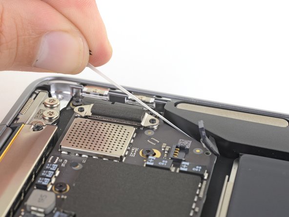
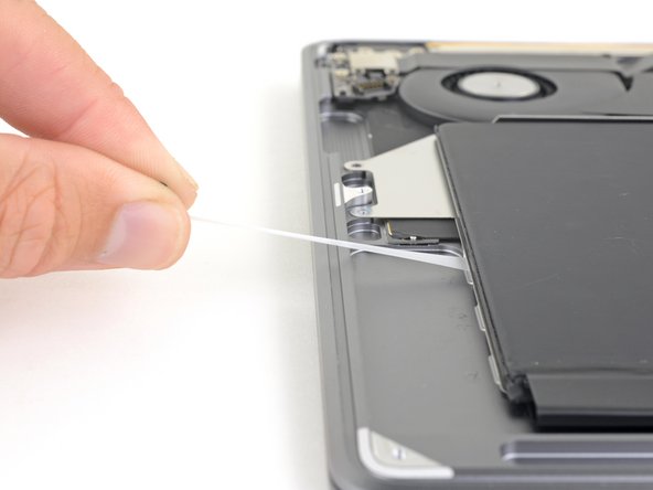
Reprenez votre pincette et soulevez la languette d'extraction noire en haut du haut-parleur droit, de façon à pouvoir la prendre en main.
-
Saisissez la languette de la bande adhésive, puis tirez dessus lentement et soigneusement pour la sortir de sous le haut-parleur.
-
Faites chauffer le haut-parleur pour ramollir l'adhésif en dessous.
-
Faites soigneusement glisser une spatule ou un médiator sous le haut-parleur pour trancher l'adhésif.
This business of pulling the adhesive out (here and with the batteries) - at first it seems impossible, but persevere. Pull it really, really, slowly - it extends to around 30cm before it's all out. I applied a bit of heat with a heat gun (at least with the batteries) and after a few failed attempts got the hang of it. When it works, it's like magic and very satisfying, and much better than giving up and prising the part off with the adhesive in place.
-
-
-
Soulevez le haut-parleur droit par le côté inférieur et retirez-le.
Step 5 the right speaker adhesive broken while removing, other end adhesive slipped out ok. But it's extremely hard to now lift up the battery, feels like I break something if I try harder.
This is not as easy as it sounds. Neither adhesive strip broke, but that bugger resists removal, because it is attached with adhesive tape to the bottom. Use different angles of attack to pry it up with steady force.
-
-
-
Avec une pincette, soulevez la languette noire d'extraction en bas du haut-parleur gauche, de façon à pouvoir la prendre en main.
-
Saisissez la languette, puis tirez lentement et soigneusement sur la bande adhésive en dessous du haut-parleur.
-
Si la bande adhésive se déchire, laissez-la et passez à l'étape suivante.
-
-
-
Reprenez votre pincette et soulevez la languette d'extraction noire en haut du haut-parleur gauche, de façon à pouvoir la prendre en main.
-
Saisissez la languette de la bande adhésive, puis tirez dessus lentement et soigneusement pour la sortir de sous le haut-parleur.
-
Faites chauffer le haut-parleur pour ramollir l'adhésif en dessous.
-
Faites soigneusement glisser une spatule ou un médiator sous le haut-parleur pour trancher l'adhésif.
-
-
-
Soulevez le haut-parleur gauche par le côté inférieur et retirez-le.
-
-
-
-
Avec un tournevis Torx T3, dévissez les deux vis de 1,4 mm qui fixent le cache du connecteur du pavé tactile.
-
Ôtez le cache.
My machine used T4 screws
Me too! I tried with T3 and it wasn’t working.
I stripped my screws trying to get them out with a t3 driver...
-
-
-
Faites glisser la pointe de la spatule sous la nappe du haut-parleur et faites levier vers le haut pour la débrancher.
-
Faites ensuite glisser l'extrémité plate de la spatule sous la nappe afin de la décoller de la carte mère.
-
-
-
Avec un tournevis Torx T3 dévissez les deux vis de 1,3 mm qui fixent le cache du connecteur du port USB-C.
-
Enlevez le cache.
There is no need to remove the logic board!!
Skip steps 16 through 28 and go to step 29 to release the trackpad cable from the battery. then follow steps to 30 through 33 to release the battery. The battery can be removed by slipping it counter-clockwise under the trackpad cable. The new battery can be slipped in place in the same way.
Much easier!!
Removing a few of the logic board screws allowed me to get the to right screw bracket under the logic board to give enough clearance as w98fxr mentioned.
This can be done, but it's very tight. Still, beats removing the logic board and the possibilities of breaking something in the process.
-
-
-
Reprenez l'extrémité plate de la spatule pour soulever le connecteur de la nappe USB-C hors de sa prise sur la carte mère.
please reconsider removing the logic board and and usb-c connector as is recommended in the prior step. i had a very difficult time reconnecting the usb-c connector
-
-
-
Gardez la spatule pour retourner le petit clapet de retenue du connecteur ZIF de la nappe de la carte son.
-
Faites glisser la nappe de la carte son hors du connecteur ZIF.
-
-
-
Prenez un tournevis Torx T3 pour retirer les deux vis de 1,4 mm qui fixent le cache des câbles d'antenne.
-
Ôtez le cache.
These are T4 screws
The MBA I just finished with were T3. I'm fairly confident with my tools as I recently updated/upgraded nearly my entire set with WiHa. I should also mention the many tools acquired from iFixit over the years have all been were exceptional lasting years. There's no doubt iFixit would have been my source but a close friend went to work for WiHa. His discount(s) & being motivated to help him was a major impact. For anyone not having such an advantage IMHO tools from iFixit are one of the best values anywhere. Let's not forget; buying from iFixit will also help to push "Right to Repair" forward. Here in Minnesota Right to repair ALMOST PASSED. Many believe it will become law during the next session! I can't tell you how proud this would make me. I would obtain as many service manuals as possible and post them all online!!! What a great dream...
-
-
-
Insérez la pointe d'une spatule (spudger) sous un des câbles d'antenne, juste à côté du connecteur.
-
Recommencez avec l'autre câble d'antenne.
Be SUPER SUPER CAREFUL pulling off the gold WiFi antenna connectors! As described, use the spludger to press up the black cable just behind the metal connector. I tried to ping them off from the bottom of the gold connector where it clips into the socket on the motherboard and ended up pulling off the SMD sockets from the motherboard - huge and costly mistake that will probably render it useless.
-
-
-
Soulevez le connecteur de la nappe d'écran avec l'extrémité plate de la spatule.
How do I reconnect display connector??
Just align the plug section of the display flex with the socket on the logic board and gently press it in until it locks in place. Do not force it but just ensure it’s correctly aligned before pushing it into the socket.
Pro tip: You can remove the two T5 screws on the LCD connector side (located to the right of the display connector and to the left of the heat shield). From there, tilt the whole skinny LCD board towards the logic board connector and gently pinch the connector in to the socket. Before laying the skinny board back down, screw in the shield from Step 15 so it doesn’t pop out of the socket again.
-
-
-
Prenez un tournevis Torx T5 pour retirer les vis suivantes :
-
Une vis de 5,5 mm
-
Trois vis de 2,6 mm
-
Deux vis de 1,9 mm
These are T5 Torx driver screws
Need torx 5 AND torx 4 driver here ;)
During re-assembly be soft when screwing in the logic board because those antenna plugs in Step 14 are quite awkward to pin back into their sockets and there is little leeway in the cables; to make this task a little easier in Step 14, secure the logic board loosely right up against the near outside edge; after re-connecting all the cables in Steps 16-9, return to Step 17 to firm up the logic board screws.
This tip was a huge help, hate these cables lol
The 5.5 mm screw goes into a hexagon standoff which may come off with the logic board being sanswiched beteen the 5.5 mm screw screw and the standoff like happened to me. Just something to be aware of. It also has a black rubber bumper over the screw which was not mentioned at all. It pulls straight off to give access to the screw.
On my board I needed to use T6 for all the screws except the rubber bumper for which I used a T7. I have a full set of small Torx drivers and tried for the best fit.
T5 fit best is all the screws on my machine
-
-
-
Faites soigneusement glisser un médiator sous la nappe du pavé tactile pour la décoller du boîtier supérieur.
-
-
-
Prenez l'extrémité plate d'une spatule pour soulever le petit clapet de retenue du connecteur ZIF du pavé tactile.
-
Faites glisser la nappe hors de la prise.
-
-
-
Faites soigneusement glisser un médiator sous la nappe du pavé tactile pour la décoller de la batterie.
-
-
-
Avec un tournevis Torx T3, dévissez les quatre vis de 2,5 mm qui fixent la batterie.
-
-
-
Prenez une pincette pour soulever la languette d'extraction noire sur le côté de la batterie de façon à pouvoir la prendre en main.
-
Saisissez la languette d'extraction de la bande adhésive, puis tirez lentement et soigneusement sur la bande adhésive qui se trouve sous la batterie.
-
Si la bande adhésive se déchire, laissez-la et passez à l'étape suivante.
-
-
-
Recommencez les deux étapes précédentes pour retirer les trois bandes adhésives de l'autre côté de la batterie.
-
Faites couler de l'alcool isopropylique le long de chaque bord de la batterie, dans les parties creuses, à l'emplacement des languettes des bandes adhésives.
-
Laissez l'alcool pénétrer dans l'adhésif pendant une ou deux minutes.
-
Servez-vous de médiators pour soulever délicatement la batterie hors du boîtier supérieur.
-
-
-
Enlevez la batterie.
-
Calibrez la nouvelle batterie : chargez-la à 100 % et laissez-la charger pendant au moins 2 heures de plus. Puis débranchez et utilisez votre ordinateur. Quand l'avertissement batterie faible s'affiche, sauvegardez votre travail et attendez que la batterie se vide et qu’il se mette en veille. Attendez au moins 5 h et rechargez-le à 100 % sans interruption.
-


Comparez votre pièce de remplacement à la pièce d'origine. Il vous faudra peut-être transférer d'éventuels composants restants ou retirer des films adhésifs de la nouvelle pièce avant de commencer le remontage.
Pour remonter votre appareil, suivez les instructions ci-dessus en sens inverse.
Déposez vos déchets électroniques dans un centre de recyclage certifié.
La réparation ne s’est pas déroulée comme prévu ? Consultez notre communauté de réponses pour obtenir de l’aide au diagnostic.
Annulation : je n'ai pas terminé ce tutoriel.
24 autres ont terminé cette réparation.
Merci à ces traducteurs :
100%


Ces traducteurs nous aident réparer le monde ! Vous voulez contribuer ?
Commencez à traduire ›

5 commentaires
Great repair guide but the logic board screws are Torx T5 (not T4) at Step 25 of guide
Thanks! I would never have guessed everything that needed to be done without this guide. Man, I HATE the tiny, tiny screws. Lost one even after sticking all the screws to tape, just in case. :( Took the full hour to put in in, but the new battery is charging like new.
Be SUPER SUPER CAREFUL pulling off the gold WiFi antenna connectors! As described, use the spludger to press up the black cable just behind the metal connector. I tried to ping them off from the bottom of the gold connector where it clips into the socket on the motherboard and ended up pulling off the SMD sockets from the motherboard - huge and costly mistake that will probably render it useless.
If the first thing you do is disconnect the battery, is it really an issue if you don’t (or can’t) disable auto-boot?
maccentric - Réponse
I agree, why disable Auto-Boot when the lid is closed and the battery is disconnected immediately? – I've never had an issue since 2016 when the feature was introduced.
stevebsiegel - Réponse
On my machine, the longest two screws were in the corners, while the other two long screws were in the middle. Perhaps previous service in the past had them replaced into the wrong place? In any case, the longest screws do seem to fit in either place. I guess 0.8mm is not very much of a difference. Seems like poor design if they could have used one size of screw.
johann beda - Réponse
Just did one, and it also had longest screws in the corners.
maccentric -
Just did another, and the long ones were in the middle. Definitely poor design and quality control.
maccentric -