Introduction
Le connecteur 72 broches est un élément matériel à l'intérieur de la console de jeu. Il dispose de 72 broches métalliques, qui entrent en contact avec les rayons métalliques à l'intérieur de la cartouche de jeu pour enregistrer le jeu. Les broches du connecteur se déforment avec le temps et la console de jeu ne peut plus enregistrer vos jeux. Ce guide vous montrera comment localiser et retirer votre connecteur 72 broches usé.
Ce dont vous avez besoin
-
-
Retirez les six vis cruciformes de 13,25 mm situées au bas de la console de jeu à l'aide d'un tournevis à tête plate n° 2,5.
-
Retournez la console de jeu vers le haut et retirez le dessus en le tirant vers le haut et loin du reste de l'appareil avec vos mains.
-
-
-
Retirez les deux vis cruciformes argentées de 17,45 mm du plateau de la cartouche à l'aide d'un tournevis cruciforme n° 2.
-
Retirez les deux vis cruciformes en bronze de 13,25 mm du plateau de la cartouche à l'aide d'un tournevis cruciforme n° 2.
-
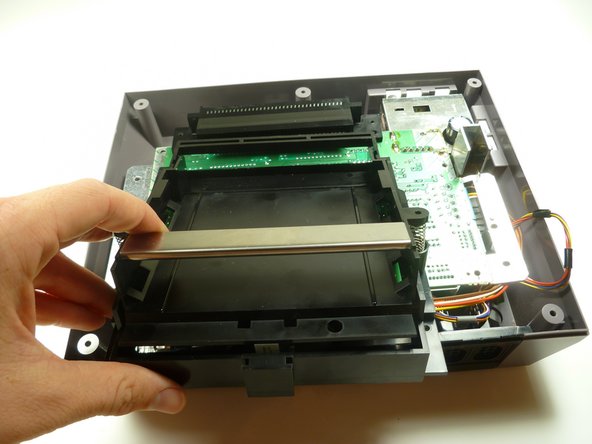
Faites glisser le plateau de la cartouche vers vous, loin du connecteur à 72 broches et de l'assemblage de la carte mère.
-
-
-
-
Sous le plateau de la cartouche se trouve une languette/lèvre noire (voir marqueur).
This is so unclear! I have no idea what tab this step is referring to.
So, it’s a year later, and I have a lot more experience with this system now. The front of the cartridge tray needs to hook under the edge of the board.
It’s much easier to get the tray on and off if you just make sure the board is unscrewed from the case. Then pick the board up a little and the tray should be much easier to slide on and off.
its when your replacing the cartridge tray, if u do it wrong the tray will feel like it's bowing up in the middle, like when u put in the screws u have to press the tray down to get the screw holes to line up / be flush, if u get the lip underneath to catch correctly there will be no issue/bow u wan't have to press down on it, or make the screws pull the tray to the motherboard, instead the tray will be flush with no pressure applied, i had no idea what he meant either until i was reversing the steps.
also not all NES are the same underneath, my tab was much less noticeable and i had one less screw to get the shield off then he showed. and 2 less screws to remove the cartridge tray.
This seemed very unclear to me at first, until I tried to replace the cart tray. I apparently didn’t get the little lip under the mobo on my first attempt, and I noticed there was a pretty decent chunk of space between the front brass screw holes and their corresponding holes on the mobo. I reseated it, and the second time I heard a little click (apparently the lip going under the mobo). This time the bottom/brass screw holes were virtually FLUSH with the mobo holes. If you see a chunk of space between the cart tray and the mobo near the brass screw holes you didn’t get the lip under the mobo.
-
-
-
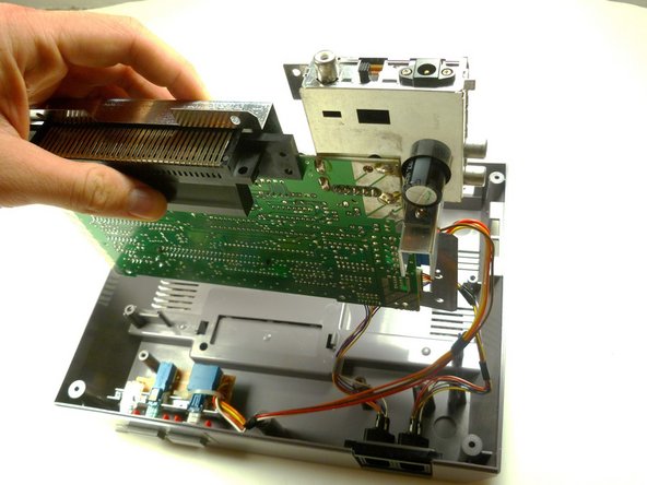
Retirez les trois vis cruciformes de 13,25 mm qui fixent la carte mère au boîtier inférieur à l'aide d'un tournevis cruciforme n°2.
-
Tirez l'assemblage de la carte mère vers le haut et hors du boîtier en plastique avec vos mains.
I did not have the bottom right screw on my NES
if you look at step 2, that shield overlaps the place where the bottom right screw would be, so there's a big gap if you put one there!
-
-
-
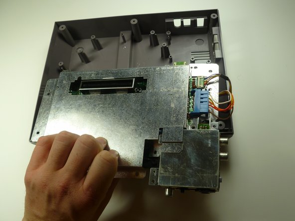
Soulevez le blindage EMI (couvercle métallique) de l'assemblage de la carte mère.
would have been really nice to show a Step 8 in pulling off the 72-PIN connector has i had to just guess that it would just pull off. it took a little force and at first i thought it was attached via something i was missing, Also anyone who wants to know when removing player 1/2 and the power and reset "big blue tab" don't pull on the wires but try and get your fingernail/jimmy on either side and nudge it going back and forth until you get some release a little, then go to other side and so same until you can get a better grip and just pull it out
-


Pour remonter votre appareil, suivez ces instructions dans l'ordre inverse.
Pour remonter votre appareil, suivez ces instructions dans l'ordre inverse.
Annulation : je n'ai pas terminé ce tutoriel.
85 autres ont terminé cette réparation.
Merci à ces traducteurs :
100%
[deleted] nous aide à réparer le monde ! Vous voulez contribuer ?
Commencez à traduire ›
Équipe

Cal Poly, Team 14-40, Forte Fall 2010 Membre de l'équipe Cal Poly, Team 14-40, Forte Fall 2010
CPSU-FORTE-F10S14G40
4 membres
20 tutoriels rédigés
13 commentaires
Because it wasn't terribly clear, the pin connector pulls off from the motherboard. Just pull straight away from the board to clear the connector. It takes some force to get it off.
And, no wires need to be disconnected either.
Very easy repair.
"How to replace your 72 pin connector"
Leaves out the steps that show how to remove the 72 pin connector.
Priceless
Um are we missing the last steps on how to actually remove the 72pin connector???
I replaced mine, and I'm still getting a solid white screen. Any ideas what else it might be?
The 10NES Chip. Mr. Glitch's Retro Reviews: HOWTO: Fix the NES Red Light Of Death (mrglitchsreviews.blogspot.com) See this guide to learn how to disable it.
I replaced my 72 pin connector and now it seems the games wont eject all the way up, it stops at like a midway point. And taking the cartridge in and out is super tough! Any ideas guys?
To remove the 72 pin connector once unscrewed just wiggle it out. Replacement connectors are very tight to insert and pull out games (this is normal).
Don’t waste your money replacing the 72 pin connector. Refurbish it without removing it from the mother board. Stop after step 2. Use a dental pic to bend the top 36 pins. It’s tedious……but free. Be careful not to over-bend them, you can fix it but it’s a pain. Take some fine grain sandpaper and fold a piece over the blade of a putty knife and duct tape it on. Insert the sandpaper clad putty knife into the 72 pin connector (straight in, straight out, don’t slide left and right while it’s in there) Move one putty knife blade width left or right and repeat until you have cleaned all the pins. Use a game that has already had it’s connectors cleaned to test the machine before you put the rf shield and the cover back on. If you can’t get the game to play re-examine the straightness of the pins you bent and run the sandpaper putty knife through there again. After you get it to work, then put the rf shield and cover back on.
I would very strongly advise against using sandpaper inside any cartridge-based system as it can leave some sand residue in the connections, which would in term wear out the contacts on the games faster.
Tsaku -
Also had problem with no picture on my Nintendo, replaced the reader, but still the same.
yo anyone no how to pop the new one on im replaceing my 72 pin but it risisting coming back on any tips so i dont break it
a pencil eraser cleans up electrical contacts nicely.
the outside screws are a little deep, plan ahead :)
Joseph McCord - Réponse
Why use a slotted driver? The screws are phillips. Both #1 and #2 work for me.
kmcrawford111 - Réponse