Introduction
Many issues with the joystick can be traced to the wires breaking between the base and the shaft on the x52(not pro, but i’m sure the same problem exists with it as well)
I’ve repaired them so many times, that the replacement wires that i’ve used, are a little to large,and are starting to bind in the shaft. So, instead of having to go in, one more freaking time, I decided to remove the problem. By replacing all the wires and adding some hot glue in the base for strain relief. And lengthening the wires about half an inch.
also found this guide, posting here for completeness.
https://imgur.com/gallery/XSJVW
Ce dont vous avez besoin
-
-
Patience :)
-
You need 2 small screw drives with a Phillips (cross) PH1 head and Torx (star) T10 head.
-
A list of screw drive heads can be hound here http://en.wikipedia.org/wiki/List_of_scr...
-
-
-
With the Phillips screwdrive unscrew the #1 to #4 screws in Fig. 1.
-
Using the Torx T10 head, unscrew the #5 (Fig. 1), #6, #7 and #8 screws (Fig. 2)
-
Using your hand, unscrew #9 (Fig. 2). Please note that you cannot completely remove this screw, but you don't need to do this anyway.
-
-
-
Carefully remove the plastic bracket and the support holding the "Pinkie trigger" by pushing it towards the trigger (Fig. 4).
-
Remove the stick cover that will expose the contacts and wiring (Fig. 5)
-
-
-
Note the small metal plate.
-
Bend it just a little from the middle so that pushing the trigger actually pushes the small blue switch inside the stick.
-
Test the trigger before putting back the plastic cover
-
-
-
-
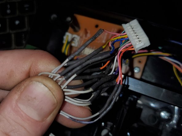
Grabbed an old IDE cable, and harvested the wire. kind of a pain to thread the wire through. In the end, I seperated 2 x 5 wire ribbon, 1x2 wire, and 1x3 wire. There are 2 posts in the shaft. The upper one likes to come out, but don't let it.(Edit, seperate all your wires if you're using ide ribbon. had to redo everything. because i didn't)
-
This metal shaft(circled), keeps on causing my wires to break.(also, logitech is being stingy on wire...) sick of soldering them back together, and the replacements I used where a bit thick, now can't find the broken wire, so replacing the whole thing.(wasn't a broken wire, but a loose contact in the plug but oh well. needed to be done)
-
-
-
once you've done the disassembly guide, remove these 2 screws.(thin screws) With a little twist, you can removed the joystick handle from the base. The roll pot just slides off once you've detached the stick.
-
Metal pin(in yellow) goes through the slot. you have to align the floating part below the shaft, twisted a little bit, and hold the spring down at the same time. This is probably the hardest part of the reassembly. you can practice without the roll pot installed, but roll pot must be installed for final assembly.
-
-
-
finished. side note, the female end was actually loose, so had to remove from white plug and squeeze the contacts back together.(used a dental pick to lift the tab that holds the contact in place.
-
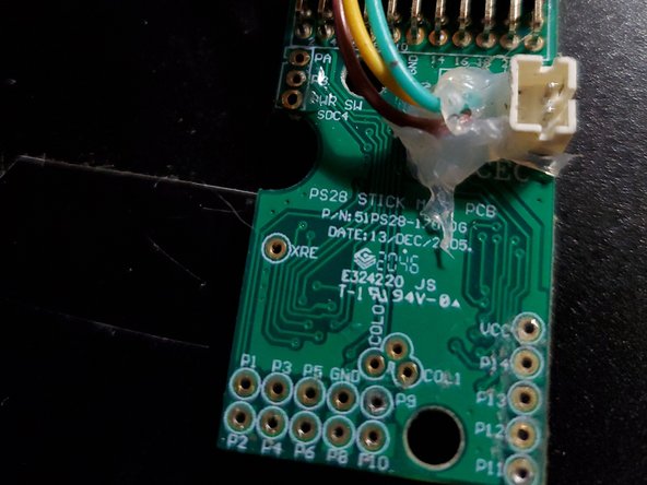
hot glue is very useful here, but not absolutely necessary. But I highly recommend for the shaft in the base as seen here.also doesn't hurt to hot glue the pcb wires as well(circled)
-
hot glue seen in base, is a previous repair.(circled yellow)
-
-
-
You'll need to have decent eyesight for this.(or magnification) Get a dental pick or a needle, or something with a sharp edge(a knife does work as well) lift up the tab that holds the contact in place, and pull the wire out.
-
The contact will have 2 sides that have become loose on the pin, so squeeze them together. I used my fingernails, but you can also use tweezers
-
This was my actual problem, THIS TIME, and it's the first time this happened on this stick for me. 99% or the time, it's been a broken wire. My problem was the ground wire contact.
-


**THIS GUIDE ASSUMES YOU KNOW HOW TO SOLDER. Through hole and joining wires.
If you don’t, youtube can help, and I suggest you practice on things you don’t care about first.
**THIS GUIDE ASSUMES YOU KNOW HOW TO SOLDER. Through hole and joining wires.
If you don’t, youtube can help, and I suggest you practice on things you don’t care about first.

Un commentaire
any chance at just a couple pictures with circles showing which pots are for which axes on the stick? I just need to figure out which one is for Yaw so I can try and repair/clean mine but can't find pictures or guide anywhere for what exactly I'm going to be looking for once I'm in there.