Cette version peut contenir des modifications incorrectes. Passez au dernier aperçu vérifié.
Ce dont vous avez besoin
-
Cette étape n’est pas traduite. Aidez à la traduire
-
Use a T5 Torx screwdriver to remove the four 4.0 mm screws on the back of the device.
-
-
Cette étape n’est pas traduite. Aidez à la traduire
-
Use a plastic opening tool to separate the display housing from from the device.
-
-
Cette étape n’est pas traduite. Aidez à la traduire
-
Gently pry back the metal flap on top of the connector.
-
Locate the two 2.0 mm black screws and unscrew using a Phillips PH00 bit. The connector will detach from the device.
-
-
-
Cette étape n’est pas traduite. Aidez à la traduire
-
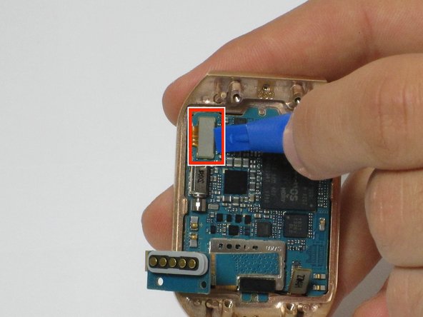
On the display, use a plastic opening tool to lift up the two ribbon cables the motherboard.
-
-
Cette étape n’est pas traduite. Aidez à la traduire
-
The motherboard is attached to the display using an adhesive
-
Using a heat gun, heat up the display for 4 to 5 minutes, making sure the move the heat gun around to distribute the heat around the display. This heats up the adhesive making the motherboard easier to remove
-
-
Cette étape n’est pas traduite. Aidez à la traduire
-
Using a plastic opening tool, carefully insert the opening tool in between the bezel and the motherboard and slide it the entire length of the logic board.
-
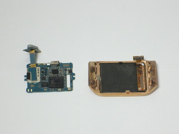
Slowly pry up the motherboard from the display.
-
-
Cette étape n’est pas traduite. Aidez à la traduire
-
The display assembly is now separated and can be replaced
-


Annulation : je n'ai pas terminé ce tutoriel.
2 autres ont terminé cette réparation.
Équipe

Cal Poly, Team 1-9, Maness Spring 2016 Membre de l'équipe Cal Poly, Team 1-9, Maness Spring 2016
CPSU-MANESS-S16S1G9
4 membres
7 tutoriels rédigés