Introduction
The DLP chip in your Samsung television is a very fine piece of technology. Texas Instruments describes it as such:
"A DLP chip's micromirrors tilt either toward the light source in a DLP projection system (ON) or away from it (OFF). This creates a light or dark pixel on the projection surface.
The bit-streamed image code entering the semiconductor directs each mirror to switch on and off up to ten thousand times per second. When a mirror is switched on more frequently than off, it reflects a light gray pixel; a mirror that's switched off more frequently reflects a darker gray pixel.
In this way, the mirrors in a DLP projection system can reflect pixels in up to 1,024 shades of gray to convert the video or graphic signal entering the DLP chip into a highly detailed grayscale image."
When your chip begins to fail (from age or excess heat) these microscopic mirrors stick either on, or off. This can lead to spots on your TV, either white ones (for those mirrors stuck in the on position) or black ones (where the mirror is stuck off).
Usually this begins with one mirror. You'll notice a white or black pixel glaring at you while watching your favorite high-def movie. Slowly, as the chip continues to fail, the spots will spread across the TV until your movies and television are almost un-watchable.
The great thing about owning a DLP television is that many of these parts are readily replaceable. The DLP chip is one of those items. Learn how with this guide!
Note that the Samsung TV uses the same Texas Instruments chip across a number of models, and with some Mitsubishi and Toshiba DLP televisions. Make sure the chip your are buying matches the model number of your TV.
Ce dont vous avez besoin
-
-
Here is a prime example of a failed DLP chip. The TV has become basically impossible to use due to the overwhelming number of stuck mirrors in the DLP chip. Let's fix it!
-
-
-
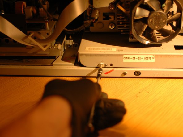
The first step when working on your DLP is to remove the lower rear cover. Begin by removing the six black Phillips screws on the center of the back of the TV.
-
There are two on the far left of the flat center of the back of the TV.
-
Then, two in the middle.
-
And finally, two on the right.
-
-
-
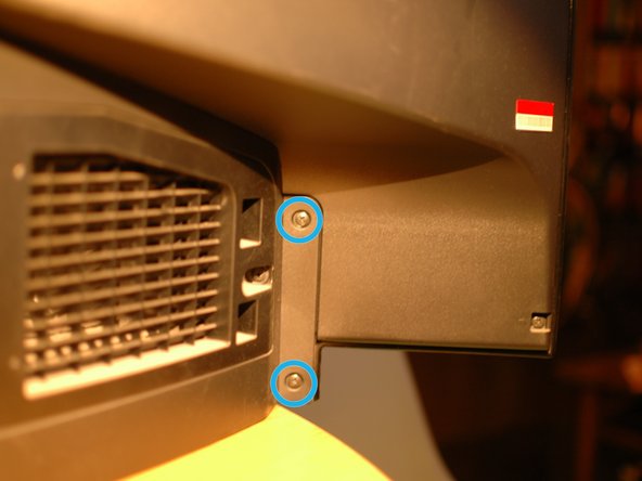
You will then find two more screws on the far left of the TV, just to the left of the A/V inputs.
-
And finally there are two more black Phillips screws on the far right, past the air intake for the bulb vent.
-
With all ten screws removed the rear cover can be pulled off. Note that there is a long vent snorkel on the far right side for the bulb that will have to clear the frame of the TV.
-
-
-
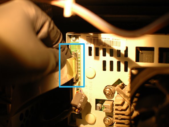
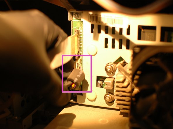
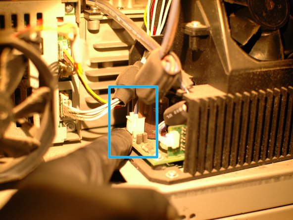
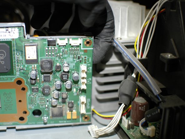
Next you will remove the upper two cables on the left hand side of the light engine, which plug in to the DMD board.
-
First, remove the upper silver ribbon cable. Press in on the top and bottom of cable end to release the small clips that hold it in the plug.
-
Then remove the second cable by pressing on the clip that holds the white cable end in to the plug and pulling it straight out at the same time.
-
-
-
-
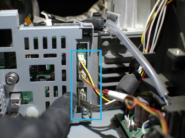
Next, proceed by removing all of the cables that connect to the DMD board.
-
At the upper right edge there is a small ribbon cable that pulls straight up to remove, and two other cables that connect with cable ends that clip in to the small plugs. Remove these three cables carefully.
-
Next, remove the three cables on the right end of the DMD board. The two upper are fan power cables, and the lower connects to the light bulb controls.
-
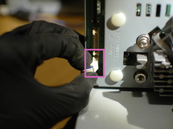
Finally, remove the lower most cable that connects to the bottom left corner of the DMD board.
-
-
-
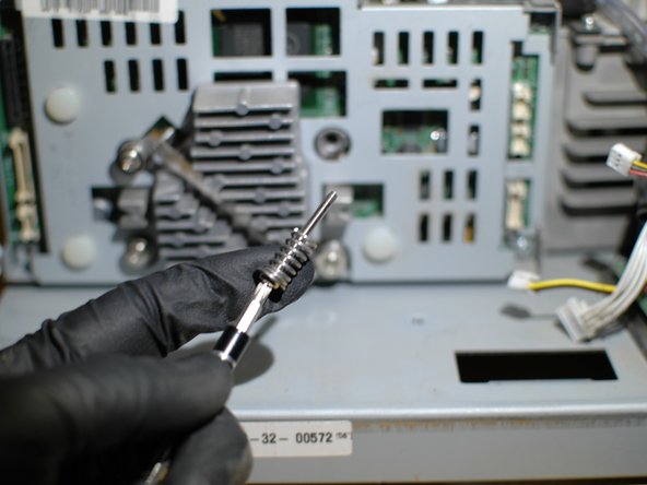
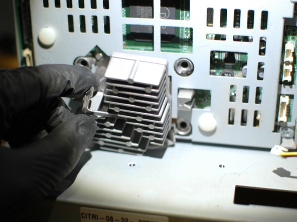
Remove the four spring-loaded screws that reside on each side of the heatsink. These screws apply pressure to the DMD board to hold it in position, under tension - once adjusted at the factory the the DMD board needs to be held in place over the long term or the picture quality will suffer.
-
See the springs that sit behind the screws in the second picture.
-
-
-
With the heatsink removed you will see the thermal pad that was installed at the factory.
-
If you plan to reuse this thermal pad with the new DLP chip be sure to keep it protected while you complete this guide.
-
There is some suggestion that inadequate thermal paste leads to the premature failure of the DLP chips on these TV's, so you may also consider removing the factory thermal pad and putting a better thermal paste like Arctic Silver on the chip itself, like you would with a computer processor.
-
If you decide to do this, at this time you can follow the manufacturer's instructions for cleaning the heatsink of the old thermal paste and, if applicable, tinting the heatsink.
-
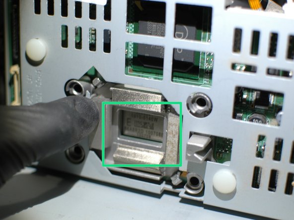
Looking through the hole where the heatsink sits you can see the top of the DLP chip. Almost there!
-
-
-
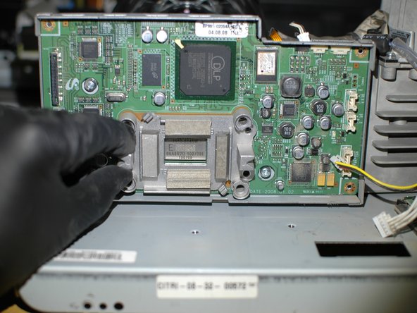
With the heatsink bracket removed the DMD board can be removed from the rear cover.
-
It can help to start removing the board by pulling out on the upper right edge.
-
Then, pull on the right side of the board.
-
The board should then pivot out from the right. It is a snug fit but it should remove with care.
-
-
-
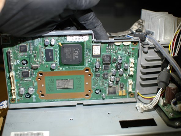
With the DMD board removed you will see the three screws again. DO NOT touch these! I just wanted to say that again!
-
With the DMD board removed you can see where the chip mates with the rest of the light engine, in the opening at the center of the cover. It is a good time to use a bit of canned air to blow dust out of this area.
-
-
-
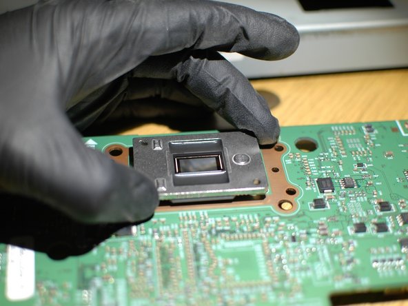
Turn the DMD board over and you will see the DLP chip.
-
If you've ever removed a computer CPU you will find this is a bit different. The chip is not held in with a "Zero Insertion Force" mechanism with a clip or lever. Instead, it is held in by the tension of the pins alone.
-
Therefore, when removing the chip, simply pull up until it releases from the board.
-
-
-
In the first picture, see the outside facing part of the chip that touches the heatsink. From the factory the top of the chip doesn't have any thermal compound on it. This is where I chose to add Arctic Silver thermal paste to help with the thermal protection of the chip. This is optional.
-
In the second picture you can see the defective mirror surface in the DLP chip. A good mirror surface should look clean with a rainbow effect. This defective mirror shows many small spots.
-
In the third picture you can see the socket that the DLP chip fits in to. When installing your replacement chip it simply pushes in.
-
-
-
While reassembly is generally the reverse of the dis-assembly, when re-installing the heatsink you should make sure it's a snug fit once the clip is installed. Wiggle the heatsink; it should move very little. If it moves too much, remove the clip and bend the ends upward so that it provides more tension when it is installed.
-


To reassemble your device, follow these instructions in reverse order.
To reassemble your device, follow these instructions in reverse order.
Annulation : je n'ai pas terminé ce tutoriel.
28 autres ont terminé cette réparation.

Équipe

22 commentaires
Perfect guide!!! I just used this and replaced chip in less than 45 minutes and now working perfectly!! Only suggestion is that I used sticky notes for each step and the corresponding screws/parts. Made it very easy to put back together. Thank you!!
Great! Glad it worked, and good idea with the sticky notes. Keep it up!
This is about as good as a guide can be . This problem just started for me .Glad i found this !
Glad to hear it Chris!