Cette version peut contenir des modifications incorrectes. Passez au dernier aperçu vérifié.
Ce dont vous avez besoin
-
Cette étape n’est pas traduite. Aidez à la traduire
-
Place the TV face down on a flat smooth surface as to not scratch the screen.
-
Using a Phillips #2 screwdriver remove the four 8mm screws attaching the stand to the TV.
-
-
Cette étape n’est pas traduite. Aidez à la traduire
-
Remove the two back panels by prying them out with your hands.
-
-
Cette étape n’est pas traduite. Aidez à la traduire
-
Using a Phillips #2 screwdriver, remove the eight 6mm Phillips screws located around the edge.
-
Using a Phillips #2 screwdriver, remove the two 6mm Phillips screws located near the inputs.
-
-
Cette étape n’est pas traduite. Aidez à la traduire
-
Using your hands, gently lift and remove the back case of the television.
-
-
Cette étape n’est pas traduite. Aidez à la traduire
-
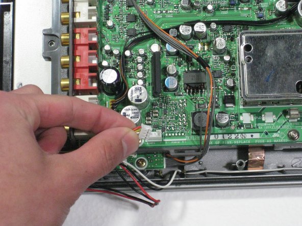
Remove the two speaker cables and the connector from the circuit board by pinching the plastic connectors and firmly pulling up.
-
-
-
Cette étape n’est pas traduite. Aidez à la traduire
-
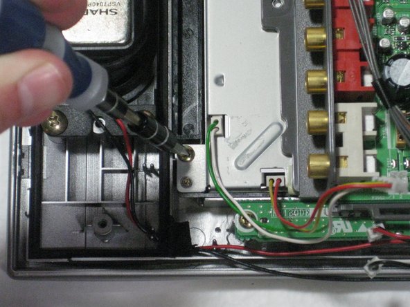
Remove the green and gray power connector from the side of the buttons panel at the top of the television.
-
Remove the green/gray to orange/gray connector from the center of the circuit board.
-
-
Cette étape n’est pas traduite. Aidez à la traduire
-
Remove the four 5mm phillips screws attaching the LCD and circuit board to the front case.
-
-
Cette étape n’est pas traduite. Aidez à la traduire
-
Lift the circuit board/LCD block from the case by lifting the near side of the circuit board and sliding it under the button frame.
-
-
Cette étape n’est pas traduite. Aidez à la traduire
-
Flip the LCD/circuit board so that the circuit board faces up.
-
-
Cette étape n’est pas traduite. Aidez à la traduire
-
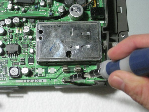
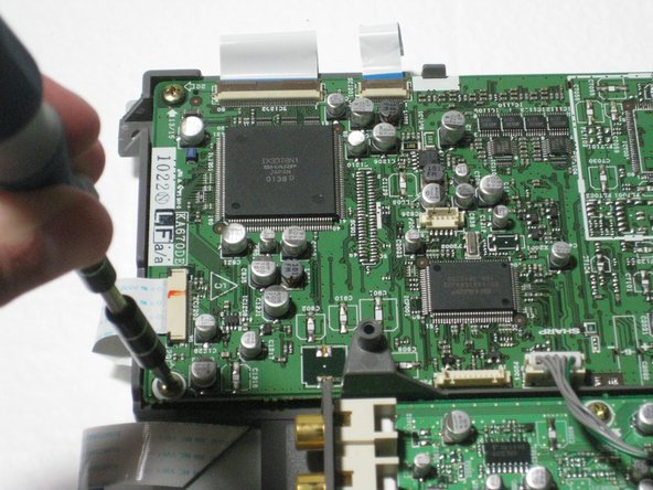
Remove the three 5mm Philips screws attaching the circuit board to the LCD.
-
Remove the five 6mm Phillips screws from the edges of the circuit board attacking it to the LCD.
-
-
Cette étape n’est pas traduite. Aidez à la traduire
-
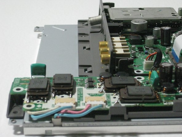
Turn the circuit board so the blue and pink side cables are facing you.
-
-
Cette étape n’est pas traduite. Aidez à la traduire
-
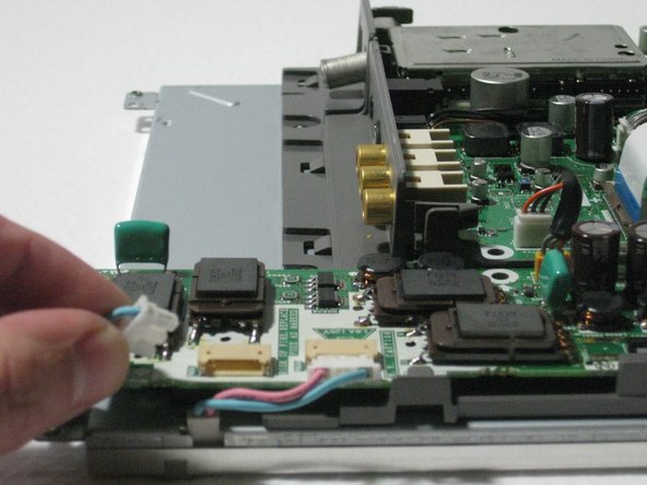
Turn the television so the right hand side is facing you.
-
Turn the television so the left hand side is facing you, and remove the ribbon cable in the same manner.
-
-
Cette étape n’est pas traduite. Aidez à la traduire
-
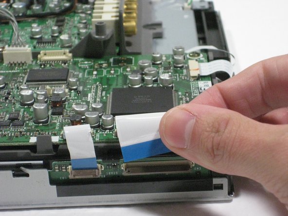
Turn the circuit board so that the left side is facing you.
-
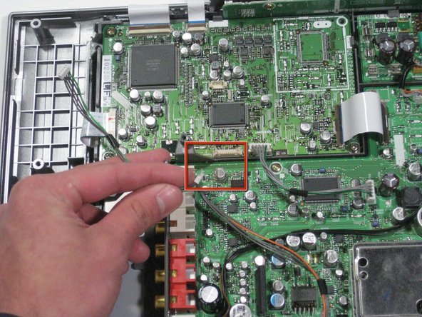
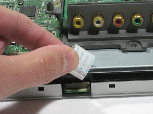
Detach the data cable from the circuit board.
-
To do this, slide your finger nail from the middle of the connector until the little black tabs rotates down toward the board as shown in the second picture.
-
-
Cette étape n’est pas traduite. Aidez à la traduire
-
Lift and remove the circuit board from the LCD frame.
-


Annulation : je n'ai pas terminé ce tutoriel.
2 autres ont terminé cette réparation.
Équipe

Cal Poly, Team 1-11, Amido Winter 2011 Membre de l'équipe Cal Poly, Team 1-11, Amido Winter 2011
CPSU-AMIDO-W11S1G11
4 membres
9 tutoriels rédigés