Cette version peut contenir des modifications incorrectes. Passez au dernier aperçu vérifié.
Ce dont vous avez besoin
-
Cette étape n’est pas traduite. Aidez à la traduire
-
Press the battery release button.
-
While pushing the battery button, slide the battery to the left.
-
-
Cette étape n’est pas traduite. Aidez à la traduire
-
Open the cassette cover.
-
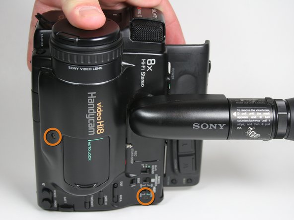
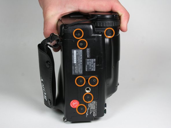
Unscrew 14 screws located on the outer casing. Three are located on the top face 2x6.8mm and 1X4.54mm, three on the left face 1x4.54mm,1x5.3mm and seven on the bottom face 5x4.54mm and 2x6.77mm.
-
-
Cette étape n’est pas traduite. Aidez à la traduire
-
Remove five screws from the right side, from bottom to top, 3x4.54mm 2x5.70mm.
-
Remove the single 4.5 mm screw from the backside.
-
-
Cette étape n’est pas traduite. Aidez à la traduire
-
Pull off the plastic tape cover by lifting it up and out of the camera base.
-
-
-
Cette étape n’est pas traduite. Aidez à la traduire
-
Disconnect the mic assembly by pulling it away from the camera base.
-
-
Cette étape n’est pas traduite. Aidez à la traduire
-
Pull the bottom part of the case away from the camera.
-
-
Cette étape n’est pas traduite. Aidez à la traduire
-
Remove the three 4.5 mm screws from the right face of the video camera.
-
-
Cette étape n’est pas traduite. Aidez à la traduire
-
Remove the single 3.6 mm screw at the front of the video camera on the circuit board.
-
-
Cette étape n’est pas traduite. Aidez à la traduire
-
Pull the audio/video inputs underneath the microphone assembly. The inputs should still be connected to the circuit board.
-
-
Cette étape n’est pas traduite. Aidez à la traduire
-
Remove two remaining 3.6 mm case screws from the front of the camera.
-
-
Cette étape n’est pas traduite. Aidez à la traduire
-
Using metal tweezers, pull out the plastic connector box on the front side.
-
Again use metal tweezers to pull out the connection box on the bottom of the camera. The right side of the case can now be removed by pulling it to the right.
-
-
Cette étape n’est pas traduite. Aidez à la traduire
-
Using metal tweezers, pull out the plastic connector box located in the center area.
-
Pull up the circuit board.
-
-
Cette étape n’est pas traduite. Aidez à la traduire
-
Remove all three screws around the lens assembly.
-
-
Cette étape n’est pas traduite. Aidez à la traduire
-
Remove three gold screws from the lens assembly.
-
-
Cette étape n’est pas traduite. Aidez à la traduire
-
Lift the lens assembly from the large circuit board.
-
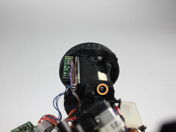
Remove the two 5.3 mm screws.
-
Remove the single 6.1 mm screw using a Phillips #000 screwdriver.
-
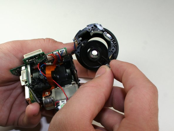
Remove the lens from the lens assembly.
-


Annulation : je n'ai pas terminé ce tutoriel.
2 autres ont terminé cette réparation.
Équipe

Cal Poly, Team 11-25, Maness Winter 2011 Membre de l'équipe Cal Poly, Team 11-25, Maness Winter 2011
CPSU-MANESS-W11S11G25
4 membres
5 tutoriels rédigés