Cette version peut contenir des modifications incorrectes. Passez au dernier aperçu vérifié.
Ce dont vous avez besoin
-
Cette étape n’est pas traduite. Aidez à la traduire
-
Unscrew the 1.9mm screw located at the top of the device with a Phillips #00 screwdriver.
-
-
Cette étape n’est pas traduite. Aidez à la traduire
-
Unscrew the 2.5mm screw located on the left side of the device with a Phillips #00 screwdriver.
-
-
Cette étape n’est pas traduite. Aidez à la traduire
-
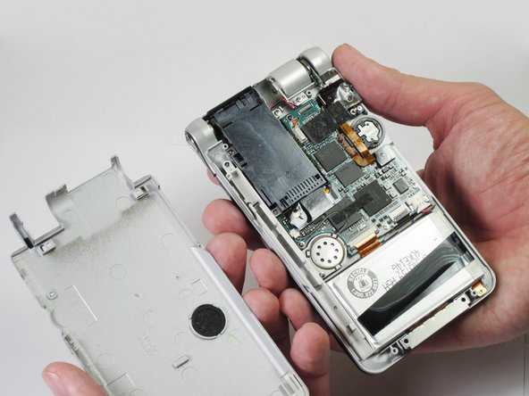
Unscrew the five 2.5mm screws on the back panel with a Phillips #00 screwdriver.
-
Remove the back panel by lifting it away with your hands.
-
-
-
Cette étape n’est pas traduite. Aidez à la traduire
-
Unscrew the 2.5mm screw on the top portion of the audio module with a Phillips #00 screwdriver.
-
-
Cette étape n’est pas traduite. Aidez à la traduire
-
Remove the tape that is holding the module down.
-
-
Cette étape n’est pas traduite. Aidez à la traduire
-
Lift up the orange ribbon cable and unscrew the two 2.5mm screws located at the corners of the audio module with a Phillips #00 screwdriver.
-
-
Cette étape n’est pas traduite. Aidez à la traduire
-
Unplug the audio module from the motherboard by disconnecting the wires by lifting the orange wire up.
-


Équipe

Cal Poly, Team 14-11, Maness Spring 2013 Membre de l'équipe Cal Poly, Team 14-11, Maness Spring 2013
CPSU-MANESS-S13S14G11
5 membres
8 tutoriels rédigés