Cette version peut contenir des modifications incorrectes. Passez au dernier aperçu vérifié.
Ce dont vous avez besoin
-
Cette étape n’est pas traduite. Aidez à la traduire
-
Heat up the back cover to soften the adhesive.
-
Place the suction cup to open a gap from top side, then insert guitar picks and slide it to cut the adhesive underneath.
-
Remove back cover.
-
-
Cette étape n’est pas traduite. Aidez à la traduire
-
Twist off 10 Phillips screws all.
-
Loosen NFC clip and flashlight clip.
-
-
Cette étape n’est pas traduite. Aidez à la traduire
-
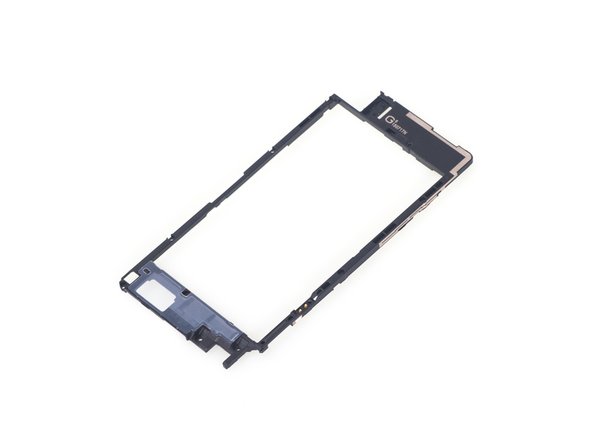
Remove the plastic bracket.
-
Pry up and remove back frame.
-
-
-
Cette étape n’est pas traduite. Aidez à la traduire
-
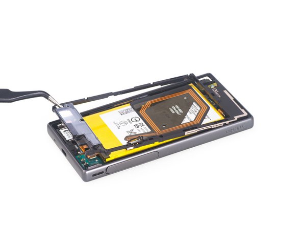
Release charging port connector.
-
Remove plastic protective bar.
-
Pry up motherboard assembly from this side. There are three flex connectors connecting the motherboard underneath. So pry up the motherboard assembly gently.
-
-
Cette étape n’est pas traduite. Aidez à la traduire
-
Push audio jack out of the slot, no adhesive underneath.
-
Release LCD flex connector and main flex connector by flipping up the white locking tab of the connector base.
-
Separate motherboard assembly from middle housing.
-
-
Cette étape n’est pas traduite. Aidez à la traduire
-
The sticker underneath LCD assembly is a little bit strong, so use heat gun to soften it for a few minutes.
-
Remove LCD with digitizer assembly carefully.
-


Annulation : je n'ai pas terminé ce tutoriel.
23 autres ont terminé cette réparation.

18 commentaires
But what kind of glue do we need to use when we reconnect the screen and the case?
screen replacement is possible without removing the back cover and logic board, similar to the Z1 compact. Simply remove the metal cover once you took the screen off to disconnect the lcd/digi cable.
Yeah, I'm confused as to why everything from the back needs to be taken out, when you have to heat up the front sticker anyways and disconnect it. Seems fairly simple to just heat up, cut side adhesive, lift, unplug.
Have you done the repair that way, Toby Liedke?