Aller au contenu principal

Wintec Filemate Clear 7" Charging Pin Replacement

  1. Wintec Filemate Clear 7" Charging Pin Replacement, Remove the Backplate: étape 1, image 1 de 1
    • Locate the four corners of the backplate.

  2. Wintec Filemate Clear 7" Charging Pin Replacement: étape 2, image 1 de 2 Wintec Filemate Clear 7" Charging Pin Replacement: étape 2, image 2 de 2
    • Pry off the backplate by inserting a spudger or plastic opening tool into each corner and popping them open.

  3. Wintec Filemate Clear 7" Charging Pin Replacement, Remove the Battery: étape 3, image 1 de 1
    • Un-stick the battery from the motherboard assembly with the plastic opening tool.

  4. Wintec Filemate Clear 7" Charging Pin Replacement: étape 4, image 1 de 1
    Outil utilisé dans cette étape :
    Tweezers
    $4.99
    J'achète
    • Desolder the battery wires from the motherboard.

    • The tweezers pictured point to the two solder joints.

  5. Wintec Filemate Clear 7" Charging Pin Replacement: étape 5, image 1 de 1
    • Fully remove the battery from the device.

  6. Attention : les étapes 6 à 10 sont issues d'un tutoriel marqué comme étant en cours.

    Wintec Filemate Clear 7" Charging Pin Replacement, Motherboard: étape 6, image 1 de 1
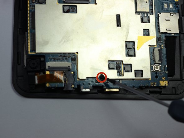
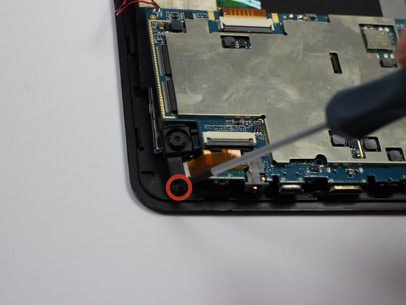
    • Locate each of the motherboard's 4 mm screws.

  7. Wintec Filemate Clear 7" Charging Pin Replacement, Unscrewing Everything: étape 7, image 1 de 3 Wintec Filemate Clear 7" Charging Pin Replacement, Unscrewing Everything: étape 7, image 2 de 3 Wintec Filemate Clear 7" Charging Pin Replacement, Unscrewing Everything: étape 7, image 3 de 3
    • Remove each of the four 4 mm screws from the motherboard pictured to the left.

    • Use a Phillips #00 precision screwdriver.

  8. Wintec Filemate Clear 7" Charging Pin Replacement, Detach the Motherboard: étape 8, image 1 de 2 Wintec Filemate Clear 7" Charging Pin Replacement, Detach the Motherboard: étape 8, image 2 de 2
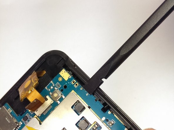
    • Use the spudger to pry the instrument array from its plastic housing.

  9. Wintec Filemate Clear 7" Charging Pin Replacement: étape 9, image 1 de 1
    • Slowly slide the spudger underneath the adhesive tape to un-sitck it.

    • Be careful not to harm the array of wires leading to this tape.

  10. Wintec Filemate Clear 7" Charging Pin Replacement: étape 10, image 1 de 1
    Outil utilisé dans cette étape :
    Tweezers
    $4.99
    J'achète
    • De-tatch the motherboard output wires from the screen using the tweezers.

  11. Wintec Filemate Clear 7" Charging Pin Replacement, Remove the Charging Pin: étape 11, image 1 de 1
    Outil utilisé dans cette étape :
    Tweezers
    $4.99
    J'achète
    • Remove the charging pin holster.

    • Clamp on the end of the holster with the tweezers and twist until it becomes detached.

    • Repeat for the other side.

  12. Wintec Filemate Clear 7" Charging Pin Replacement: étape 12, image 1 de 1
    • Clamp onto the charging pin and twist up until it pops out of place.

Conclusion

To reassemble your device, follow these instructions in reverse order. The charging pin holster needs to be soldered back into place.

Une autre personne a terminé cette réparation.

Nicholas Ferraro

Membre depuis le 01/20/15

431 Réputation

6 tutoriels rédigés

Équipe

USF Tampa, Team 19-6, Blackwell Spring 2014 Membre de l'équipe USF Tampa, Team 19-6, Blackwell Spring 2014

USFT-BLACKWELL-S14S19G6

3 membres

11 tutoriels rédigés

0 commentaires

Ajouter un commentaire

Nombre de vues :

Dernières 24 heures : 0

7 derniers jours : 0

30 derniers jours : 5

Total : 129