Cette version peut contenir des modifications incorrectes. Passez au dernier aperçu vérifié.
Ce dont vous avez besoin
-
Cette étape n’est pas traduite. Aidez à la traduire
-
In the following steps, you will remove the top vent, secured to the top panel by the thirteen clips shown.
-
-
Cette étape n’est pas traduite. Aidez à la traduire
-
Orient the console so that the words "XBOX 360" on the sides are right-side up, and the faceplate is facing to the left.
-
Insert a metal spudger between the top vent and the top bezel near the rear of the Xbox.
-
Rotate the spudger away from the console, prying the edge of the fan vent up until the two plastic clips come free.
-
-
Cette étape n’est pas traduite. Aidez à la traduire
-
Insert a metal spudger between the fan vent and top bezel along the left side of the console.
-
In the same manner described above, begin prying the left side of the top vent away from the top bezel.
-
Continue prying along the left side of the device, freeing all the clips on that side.
-
-
Cette étape n’est pas traduite. Aidez à la traduire
-
Lift the fan vent up from the freed left side to disengage the clips along the right side.
-
Remove the entire fan vent.
-
-
Cette étape n’est pas traduite. Aidez à la traduire
-
In the following steps, you will be releasing the six clips highlighted in red.
-
-
Cette étape n’est pas traduite. Aidez à la traduire
-
Insert a metal spudger through the front-most slit on the left edge of the top bezel and between the bottom edge of the clip and the left case, as described above.
-
Simultaneously rotate the spudger away from the console and pull up on the top bezel to free the clip.
-
-
Cette étape n’est pas traduite. Aidez à la traduire
-
Using the same method described above, free the two remaining clips along the left edge of the top bezel.
-
-
Cette étape n’est pas traduite. Aidez à la traduire
-
Grab the entire top panel with your hands, lift up the entire left edge high enough to rest the separated clips on top of the left case.
-
-
Cette étape n’est pas traduite. Aidez à la traduire
-
Rotate the console so that the rear of the Xbox 360 S is facing to the right, and the right case is facing you.
-
Insert a metal spudger through the rear-most slit on the right edge of the top bezel and between the bottom edge of the clip and the right case.
-
While lifting up on the top bezel with your fingers, rotate the spudger away from the console to free the clip.
-
-
Cette étape n’est pas traduite. Aidez à la traduire
-
In the same manner as described in the previous steps, release the middle and front clips along the right edge of the top panel.
-
-
-
Déplacez vers la gauche le loquet qui maintient en place le cache du disque dur.
-
Retirez le cache du disque dur de la console.
-
-
Cette étape n’est pas traduite. Aidez à la traduire
-
It is attached to the bottom panel by the seven clips shown.
-
-
Cette étape n’est pas traduite. Aidez à la traduire
-
Insert a metal spudger between the black bottom vent and the silver rim of the bottom bezel, in the rear right corner of the vent.
-
Rotate the spudger away from the console, prying the vent up from the bottom bezel.
-
-
Cette étape n’est pas traduite. Aidez à la traduire
-
In the same manner as described above, pry the two remaining clips on the bottom right edge.
-
-
Cette étape n’est pas traduite. Aidez à la traduire
-
Remove the bottom vent by lifting it away from the bottom bezel.
-
-
Cette étape n’est pas traduite. Aidez à la traduire
-
The clips shown in red can be detached by inserting a metal spudger underneath the bottom edge of the clip. Once underneath the bottom edge, simply prying away from the console will free the clip.
-
-
Cette étape n’est pas traduite. Aidez à la traduire
-
Insert a metal spudger through the slit near the rear left corner of the bottom bezel.
-
Rotate the spudger away from the device while lifting the rear bezel up with the other hand.
-
-
Cette étape n’est pas traduite. Aidez à la traduire
-
Insert a metal spudger through the left middle slit of the bottom bezel, and between the bottom edge of the clip and the left case.
-
Simultaneously pull the bottom bezel up and rotate the spudger away from the console to free the clip.
-
In a similar fashion, free the clip at the front of the bottom bezel's left edge.
-
-
-
Cette étape n’est pas traduite. Aidez à la traduire
-
Insert the spudger into the rear-most slit on the right edge of the bottom bezel, and wedge it behind the clip by pushing the spudger down while pushing the tip of the spudger against the right case.
-
Simultaneously release the clip and pull the bottom bezel up.
-
-
Cette étape n’est pas traduite. Aidez à la traduire
-
Insert a spudger between the silver rim and bottom bezel directly above the clip shown.
-
Release the clip while pulling up on the bottom bezel.
-
-
Cette étape n’est pas traduite. Aidez à la traduire
-
Lift the left edge of the bottom bezel up enough to gain clearance.
-
Insert a metal spudger behind the left edge of the last clip, and push the clip away from the right case.
-
-
Cette étape n’est pas traduite. Aidez à la traduire
-
Locate the two clips connecting the right and left case along the top edge of the console, behind the Wi-Fi card.
-
While pushing the left and right case away from each other with one hand, pry the clips away from the case with a metal spudger.
-
-
Cette étape n’est pas traduite. Aidez à la traduire
-
Insert a spudger between the right and left cases to hold them separate while you work elsewhere.
-
-
Cette étape n’est pas traduite. Aidez à la traduire
-
While pushing the left and right cases apart with one hand, free one clip located beside the hard drive slot.
-
-
Cette étape n’est pas traduite. Aidez à la traduire
-
Place another spudger between the left and right cases directly below the clip.
-
-
Cette étape n’est pas traduite. Aidez à la traduire
-
Insert the flat edge of a metal spudger between the left and right cases where the warranty sticker used to be.
-
Pry the left case upwards to form a gap between the two cases, and slide the spudger in toward the left case.
-
Rotate the spudger upward to release the last clip.
-
-
Cette étape n’est pas traduite. Aidez à la traduire
-
Release one clip in the front left corner of the top edge securing the left case to the faceplate.
-
-
Cette étape n’est pas traduite. Aidez à la traduire
-
Flip the console over so the bottom is facing upward.
-
Release one clip in the front left corner of the bottom edge securing the left case to the faceplate.
-
Rotate the left case away from the device to release the last two inner clips.
-
Remove the left case.
-
-
Cette étape n’est pas traduite. Aidez à la traduire
-
Release the clip near the front right corner of the top edge securing the right case to the faceplate.
-
-
Cette étape n’est pas traduite. Aidez à la traduire
-
Release the clip in the bottom right corner of the top edge securing the right case to the front case.
-
-
Cette étape n’est pas traduite. Aidez à la traduire
-
Lift the left edge of the faceplate upward to release the last two clips securing the faceplate to the right case.
-
Detach the faceplate from the rest of the device.
-
-
Cette étape n’est pas traduite. Aidez à la traduire
-
Using a spudger or fingernail, lift the clear blue tab away from the connector.
-
Slide the locking tab on the power switch board cable connector toward the top of the console.
-
Pull the power switch cable straight out of the connector.
-
The faceplate is now free of the rest of the console.
-
-
Cette étape n’est pas traduite. Aidez à la traduire
-
Remove the two 5.6 mm T8 Torx screws securing the RF module to the metal case.
-
-
Cette étape n’est pas traduite. Aidez à la traduire
-
Pull the board directly away from the Xbox to remove it.
-
-
Cette étape n’est pas traduite. Aidez à la traduire
-
Remove the single T10 Torx screw holding in the wireless card.
-
Pull the Wi-Fi Board out of the console.
-
-
Cette étape n’est pas traduite. Aidez à la traduire
-
Remove the large white warranty sticker from the metal frame to expose a screw.
-
-
Cette étape n’est pas traduite. Aidez à la traduire
-
Remove the five 55.5 mm T10 Torx screws securing the right case to the metal frame.
-
-
Cette étape n’est pas traduite. Aidez à la traduire
-
Disconnect the optical drive data cable from the back of the optical drive.
-
Disconnect the power cable from the back of the optical drive.
-
-
Cette étape n’est pas traduite. Aidez à la traduire
-
Remove the single 11.3 mm gold T10 Torx screw from the hole marked "G."
-
-
Cette étape n’est pas traduite. Aidez à la traduire
-
Remove the single 9.2 mm T10 Torx screw securing the hard drive cable connector to the plastic bracket.
-
Lift the hard drive cable connector off the hard drive bracket.
-
-
Cette étape n’est pas traduite. Aidez à la traduire
-
Remove the 11.3 mm T10 Torx screw holding the hard drive bracket to the metal frame, near the DC-In port.
-
-
Cette étape n’est pas traduite. Aidez à la traduire
-
Lift the hard drive bracket out of the metal frame.
-
-
Cette étape n’est pas traduite. Aidez à la traduire
-
Disconnect the fan cable by pulling its connector off the logic board.
-
-
Cette étape n’est pas traduite. Aidez à la traduire
-
Unscrew the two 11.7 mm Phillips screws securing the fan to the heat sink in the bottom right and top left corners of the fan.
-
Remove the fan from the logic board assembly.
-
-
Cette étape n’est pas traduite. Aidez à la traduire
-
There are a total of 10 screws holding the logic board assembly to the metal case:
-
Five 11.3 mm silver T10 Torx screws, in the holes marked "M", "N", "P", "R", and "T".
-
Four 5.6 mm black T9 Torx screws in the holes marked "D", "E", "J", and "K".
-
A single 11.3 mm gold T10 Torx screw in the hole marked "A".
-
-
Cette étape n’est pas traduite. Aidez à la traduire
-
Lift the optical drive retaining bracket off the logic board.
-
-
Cette étape n’est pas traduite. Aidez à la traduire
-
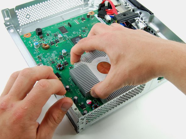
Grab the heat sink with one hand, and hold the metal frame with the other.
-
Lift the logic board assembly out of the metal frame.
-
-
Cette étape n’est pas traduite. Aidez à la traduire
-
Starting at the front left corner of the x-clamp, insert a 1.5 mm flathead screwdriver between the heat sink's peg and the x-clamp's hook.
-
-
Cette étape n’est pas traduite. Aidez à la traduire
-
In the same manner described above, release the rear right hook of the x-clamp.
-
-
Cette étape n’est pas traduite. Aidez à la traduire
-
In the same manner described above, release the rear left hook of the x-clamp.
-
-
Cette étape n’est pas traduite. Aidez à la traduire
-
Lift the x-clamp off the back of the logic board.
-


Annulation : je n'ai pas terminé ce tutoriel.
68 autres ont terminé cette réparation.

16 commentaires
This is a great guide. Thank you for taking the time to make it.
Intercooler guys, purchase an intercooler and save yourself from this hassle
I had problems getting the x-bracket off the back (step 54-57).
I found this video using a pair of needle nose pliers that helped me immensely with this step:
I think we all ended up finding that video...
Thank you for taking the time to make this very instructional guide