Cette version peut contenir des modifications incorrectes. Passez au dernier aperçu vérifié.
Ce dont vous avez besoin
-
Cette étape n’est pas traduite. Aidez à la traduire
-
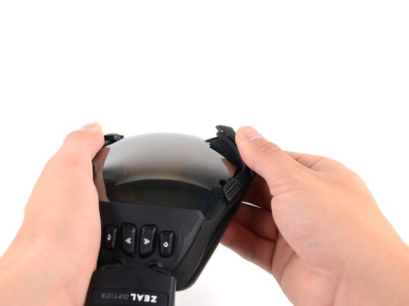
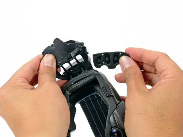
Hold the iON in your hands with your thumbs on the clips next to the middle of the lens.
-
Pull the rubber housing apart to release the first two clips.
-
-
Cette étape n’est pas traduite. Aidez à la traduire
-
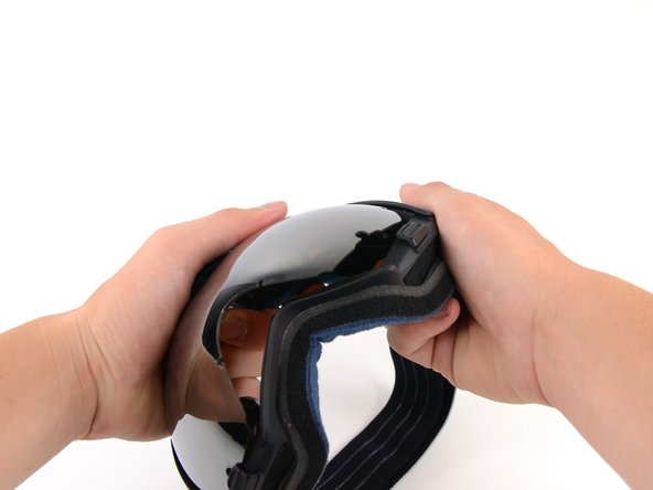
Grab the inside of the plastic nose rest with your thumb and index finger.
-
Rotate the nose rest upwards until you feel that it is free from the lens.
-
-
Cette étape n’est pas traduite. Aidez à la traduire
-
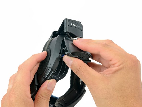
Grab the top of the goggle frame that holds the camera assembly.
-
Rotate the frame outwards until you feel that the clips inside it are free.
-
-
Cette étape n’est pas traduite. Aidez à la traduire
-
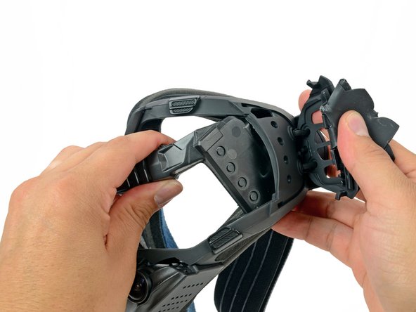
While firmly holding the goggles with the palm of one hand, grab the top right corner of the frame and rotate it away from the lens.
-
-
Cette étape n’est pas traduite. Aidez à la traduire
-
While holding the goggles in one hand, use the other to grab the lens from opposite ends, and rotate it out of the housing and away from any remaining clips.
-
-
Cette étape n’est pas traduite. Aidez à la traduire
-
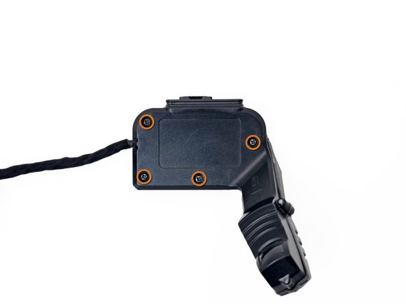
Remove the four 7.1 mm Phillips screws securing the camera housing to the goggle frame.
-
-
Cette étape n’est pas traduite. Aidez à la traduire
-
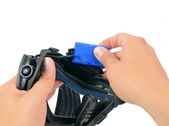
Peel back the rubber battery cover from the inner left side of the frame.
-
While firmly holding the battery cover, pull the bottom of the strap mount cover up and off of the frame
-
-
Cette étape n’est pas traduite. Aidez à la traduire
-
Once the bottom is free, continue pulling to free the top of the strap mount cover from the frame.
-
-
Cette étape n’est pas traduite. Aidez à la traduire
-
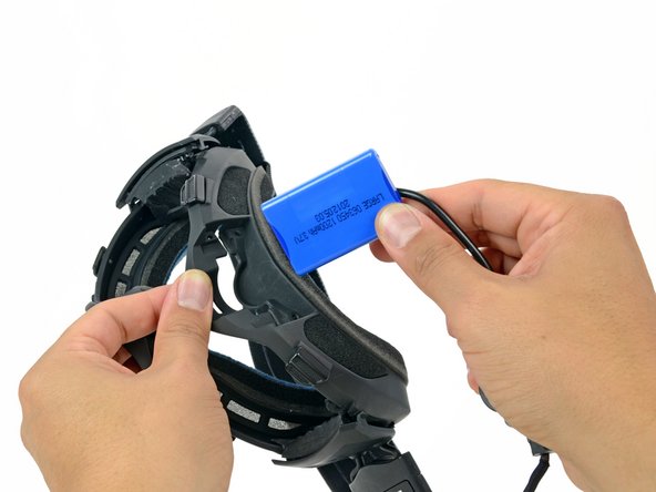
Pull the battery out of its recess in the frame.
-
-
-
Cette étape n’est pas traduite. Aidez à la traduire
-
Peel the rubber keypad cover up from the inner right side of the frame.
-
While firmly holding the keypad cover, pull the top of the strap mount cover up and off of the frame
-
-
Cette étape n’est pas traduite. Aidez à la traduire
-
Once the bottom is free, continue pulling to free the bottom of the strap mount cover from the frame.
-
-
Cette étape n’est pas traduite. Aidez à la traduire
-
Hold the strap mount cover away from the frame and remove the keypad.
-
-
Cette étape n’est pas traduite. Aidez à la traduire
-
Grab the viewfinder housing and pull it out of its recess.
-
-
Cette étape n’est pas traduite. Aidez à la traduire
-
Place one of your hands near the center of the frame with your thumb next to the camera housing.
-
With your other hand, grab the camera housing and pull it up and out of the frame.
-
-
Cette étape n’est pas traduite. Aidez à la traduire
-
Remove the viewfinder assembly by pulling it through the opening in the top of the frame.
-
-
Cette étape n’est pas traduite. Aidez à la traduire
-
In the same manner described above, remove the battery from the frame.
-
-
Cette étape n’est pas traduite. Aidez à la traduire
-
Remove the two 7.5 mm Phillips screws on the front of the viewfinder housing.
-
Remove the four 7.1 mm Phillips screws from the back of the viewfinder housing.
-
-
Cette étape n’est pas traduite. Aidez à la traduire
-
Pull the two halves of the viewfinder housing apart.
-
-
Cette étape n’est pas traduite. Aidez à la traduire
-
Use the tip of a spudger to flip up the retaining flap on the LCD ribbon cable ZIF connector.
-
-
Cette étape n’est pas traduite. Aidez à la traduire
-
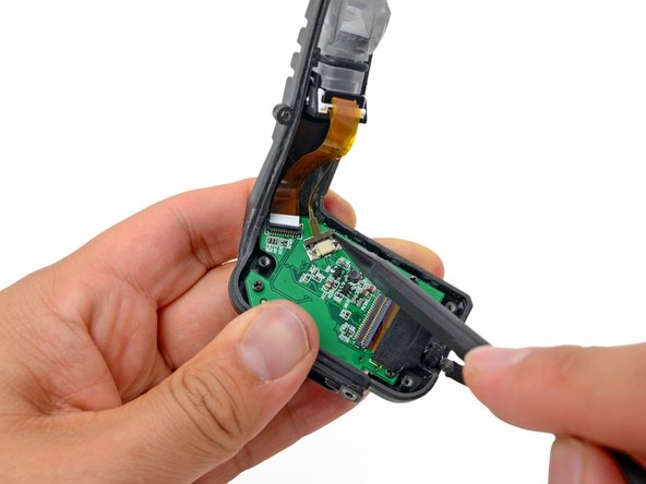
Use the tip of a spudger to push out the retaining clip on the viewfinder backlight ribbon cable ZIF connector.
-
-
Cette étape n’est pas traduite. Aidez à la traduire
-
Using your fingers or tweezers, gently pull out the backlight ribbon cable from its connector on the button board.
-
-
Cette étape n’est pas traduite. Aidez à la traduire
-
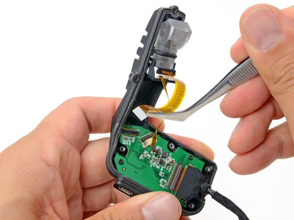
Using your fingers or tweezers, remove the LCD ribbon cable from its connector on the button board.
-
-
Cette étape n’est pas traduite. Aidez à la traduire
-
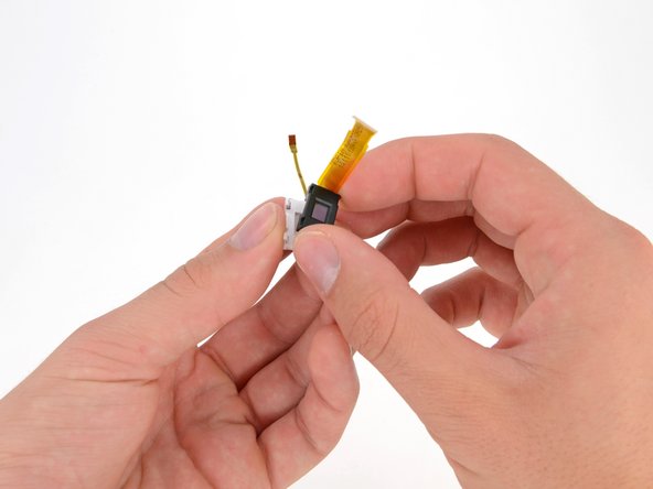
Remove the viewfinder lens assembly from the viewfinder housing.
-
-
Cette étape n’est pas traduite. Aidez à la traduire
-
Use your thumbs to lift the tabs holding the viewfinder lens to the LCD assembly.
-
Pull the viewfinder lens off of the viewfinder LCD.
-
-
Cette étape n’est pas traduite. Aidez à la traduire
-
Use your thumb to push the LCD bracket tab away from the LCD.
-
Remove the LCD bracket from the LCD and backlight.
-
-
Cette étape n’est pas traduite. Aidez à la traduire
-
Using your thumbs, pull the four white tabs on the backlight away from the LCD panel.
-
Remove the LCD from the backlight.
-