Cette version peut contenir des modifications incorrectes. Passez au dernier aperçu vérifié.
Ce dont vous avez besoin
-
Cette étape n’est pas traduite. Aidez à la traduire
-
Use a coin to rotate the battery locking screw 90 degrees clockwise.
-
Lift the battery out of the computer.
-
-
Cette étape n’est pas traduite. Aidez à la traduire
-
Pull the keyboard release tabs toward you and lift up on the keyboard until it pops free.
-
If the keyboard does not come free, use a small flathead screwdriver to turn the keyboard locking screw 180 degrees in either direction and try again.
-
Flip the keyboard over, away from the screen, and rest it face-down on the trackpad area.
-
-
Cette étape n’est pas traduite. Aidez à la traduire
-
Push the wire clasp toward the Airport card and pull it up to free it from the RAM shield.
-
-
Cette étape n’est pas traduite. Aidez à la traduire
-
Grasp the clear plastic tab on the Airport card and pull toward the right.
-
-
Cette étape n’est pas traduite. Aidez à la traduire
-
Hold the Airport card in one hand and use your other hand to remove the antenna cable.
-
-
Cette étape n’est pas traduite. Aidez à la traduire
-
Remove the two 2.5 mm Phillips screws that secure the RAM shield.
-
-
Cette étape n’est pas traduite. Aidez à la traduire
-
Grasp the metal bracket on top of the RAM shield and pull upward to remove the shield.
-
-
Cette étape n’est pas traduite. Aidez à la traduire
-
Pull the keyboard cable up from the logic board, holding the cable as close to the connector as possible.
-
-
Cette étape n’est pas traduite. Aidez à la traduire
-
Your laptop should look approximately like this.
-
-
Cette étape n’est pas traduite. Aidez à la traduire
-
Use a pin (or anything you like) to remove the three rubber feet from the lower case.
-
-
Cette étape n’est pas traduite. Aidez à la traduire
-
Remove the three 5.2 mm newly-revealed Phillips screws.
-
-
Cette étape n’est pas traduite. Aidez à la traduire
-
Use a spudger or small flathead screwdriver to pry up the three metal rings that housed the rubber bumpers.
-
-
Cette étape n’est pas traduite. Aidez à la traduire
-
Remove the one 10 mm and two 20 mm hex screws using a 2mm hex. Alternatively, a T8 Torx screwdriver key will do.
-
-
Cette étape n’est pas traduite. Aidez à la traduire
-
Remove the two 4.2 mm Phillips screws on either side of the battery contacts.
-
-
Cette étape n’est pas traduite. Aidez à la traduire
-
Breathe deeply. Trying times are ahead, but we promise the lower case does come off.
-
Push the thin rims of the lower case surrounding the battery compartment in, bending them past the tabs, and then lift up to free that corner of the lower case.
-
-
-
Cette étape n’est pas traduite. Aidez à la traduire
-
There is a slot on the wall of the battery compartment that locks the lower case in place. Use a small flathead screwdriver to pry out the slot's lower rim and pull up on the lower case to free the slot from the tabs holding it.
-
-
Cette étape n’est pas traduite. Aidez à la traduire
-
Run a spudger along the seam between the lower case and upper case on the front of the computer to free the tabs locking the lower case. Pull up on the lower case and continue to use the spudger as necessary until you hear three distinct clicks.
-
-
Cette étape n’est pas traduite. Aidez à la traduire
-
Continue to run the spudger around the front, right corner. There are two tabs on the port side of the computer, one near the front corner and one near the sound out port.
-
-
Cette étape n’est pas traduite. Aidez à la traduire
-
Once the front and sides of the lower case are free, turn the computer so that the back is facing you and pull the lower case up and toward you until the back tabs pop free (it may be helpful to jiggle the case up and down).
-
-
Cette étape n’est pas traduite. Aidez à la traduire
-
Remove the small greasy springs with white plastic caps from either side of the battery contacts.
-
-
Cette étape n’est pas traduite. Aidez à la traduire
-
Remove the following 4 screws on the bottom of the computer:
-
Two 3 mm Phillips from the left side of the computer.
-
One 4.5 mm Phillips near the latch mechanism (this screw may be missing in 800 MHz iBooks)
-
One 14.2 mm Phillips near the front, right corner.
-
-
Cette étape n’est pas traduite. Aidez à la traduire
-
Use a straightened paperclip to open the optical drive tray.
-
-
Cette étape n’est pas traduite. Aidez à la traduire
-
Pull the optical drive out just enough so that you can access and remove a Phillips screw near the battery compartment.
-
-
Cette étape n’est pas traduite. Aidez à la traduire
-
Pull the optical drive a bit more so that you can access and remove a second Phillips screw near the power receptacle.
-
-
Cette étape n’est pas traduite. Aidez à la traduire
-
Turn over the computer and open it.
-
Use tweezers (or a refrigerator magnet) to remove the magnet covering a Phillips screw near the middle of the computer.
-
-
Cette étape n’est pas traduite. Aidez à la traduire
-
Remove the following 4 screws on the edges of the keyboard area.
-
One 4.5 mm Phillips underneath where the magnet was.
-
Three 6 mm Phillips in plastic depressions.
-
-
Cette étape n’est pas traduite. Aidez à la traduire
-
Peel up the foil tape covering the speaker cable near the ports.
-
-
Cette étape n’est pas traduite. Aidez à la traduire
-
1) With your fingernails, grasp the locking bar on either side and pull up a small amount (about 1/16" or 2 mm).
-
2) After disengaging the locking bar, slide the cable out of the connector.
-
-
Cette étape n’est pas traduite. Aidez à la traduire
-
Loosen the trackpad connector by pulling the top piece up slightly, freeing the trackpad ribbon.
-
Slide the orange trackpad ribbon out of the connector.
-
-
Cette étape n’est pas traduite. Aidez à la traduire
-
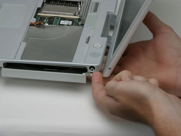
Lift the upper case from the left side and use your other hand to pull out the right side in order to clear the power receptacle.
-
-
Cette étape n’est pas traduite. Aidez à la traduire
-
Lift the upper case enough to disconnect the blue and white power cable from the logic board. Using your fingernails or a dental pick, carefully pry the connector from its socket. Make sure you're pulling only on the connector and not on the socket.
-
-
Cette étape n’est pas traduite. Aidez à la traduire
-
Lift the upper case off completely and disconnect the red and black speaker cable from the logic board. As before, make sure you're pulling only on the connector and not on the socket.
-
-
Cette étape n’est pas traduite. Aidez à la traduire
-
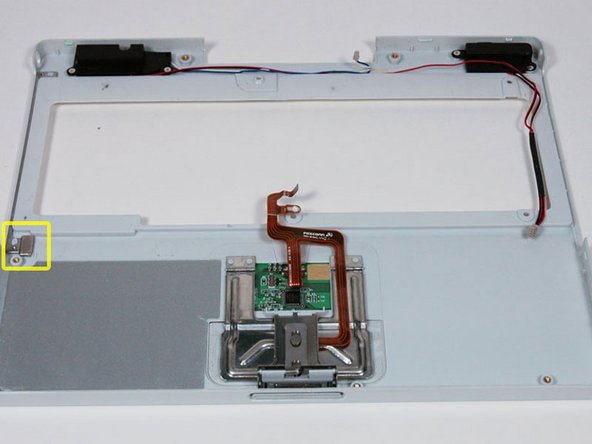
Your laptop should look approximately like this.
-
-
Cette étape n’est pas traduite. Aidez à la traduire
-
Remove the following 14 screws (some models may be missing a couple of screws):
-
One 2.5 mm Phillips.
-
Six 3.5 mm Phillips.
-
One 4.5 mm Phillips near the sleep light with a small shaft.
-
Two 4.5 mm Phillips with larger shafts.
-
Four 5 mm Phillips
-
If a screw is inserted in the left hole, the 14.2 mm screw in step 24 can not be inserted to hold the top case down.
-
-
Cette étape n’est pas traduite. Aidez à la traduire
-
Peel back three strips of yellow tape in the bottom left corner.
-
Peel back one strip of foil tape in the upper left corner and another near where the trackpad connects to the logic board.
-
-
Cette étape n’est pas traduite. Aidez à la traduire
-
Lift the top shield up from the right side, minding the upper left corner, which may catch on the metal framework.
-
-
Cette étape n’est pas traduite. Aidez à la traduire
-
Your laptop should look approximately like this.
-
-
Cette étape n’est pas traduite. Aidez à la traduire
-
Use the transparent orange loop to disconnect the large orange ribbon cable from the logic board.
-
-
Cette étape n’est pas traduite. Aidez à la traduire
-
Lift up the front edge of the hard drive.
-
Peel back the black tape to free the microphone cable from the hard drive.
-
-
Cette étape n’est pas traduite. Aidez à la traduire
-
Use the transparent orange loop to disconnect the hard drive ribbon cable from the hard drive.
-
-
Cette étape n’est pas traduite. Aidez à la traduire
-
Your laptop should look approximately like this.
-
-
Cette étape n’est pas traduite. Aidez à la traduire
-
Your hard drive should look approximately like this.
-
-
Cette étape n’est pas traduite. Aidez à la traduire
-
Remove the metal brackets from either side of the hard drive (if they're still there).
-
Remove two T8 Torx screws from either side of the hard drive (four screws total).
-


Annulation : je n'ai pas terminé ce tutoriel.
127 autres ont terminé cette réparation.
Pièces jointes

9 commentaires
Thanks for the clear guide ! Being an Amateur your 44 steps have shown me that I won't even go there !!
My hard drive in the iBook g3 is not functioning as it should. Are there any external drive startup options for an iBook of this age ?
I got as far as step 13, but two of the hex screws would not come out of the case. They appear to be loosened, but I can't remove them from the case. I then looked through the remaining steps and decided it was not worth my time to continue. I guess I will need to take this old iBook to someone who can do it for me.
The proccess is long but is real needed .
All still alive in the end, me and my Ibook g3.
tnks for this help.
Thank you!!!! Just pulling old hard drives and recycling, I cannot believe how tough these old g3’s were to get the hard drive out! Thanks again!!! Mike
These steps are all out of order, man!