Cette version peut contenir des modifications incorrectes. Passez au dernier aperçu vérifié.
Ce dont vous avez besoin
-
-
Débranchez tous les câbles de l'ordinateur, y compris le câble d'alimentation. Posez l'ordinateur face cachée, en appuyant le cou et la base avec un chiffon doux sous l'écran.
-
-
Cette étape n’est pas traduite. Aidez à la traduire
-
Open the housing plate.
-
A fixed plug connector between the logic board and upper unit will cause some resistance. Pull gently but firmly.
-
-
-
Cette étape n’est pas traduite. Aidez à la traduire
-
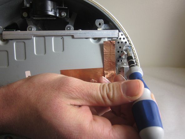
Remove the 2 torx 10mm screws on the EMI shield
-
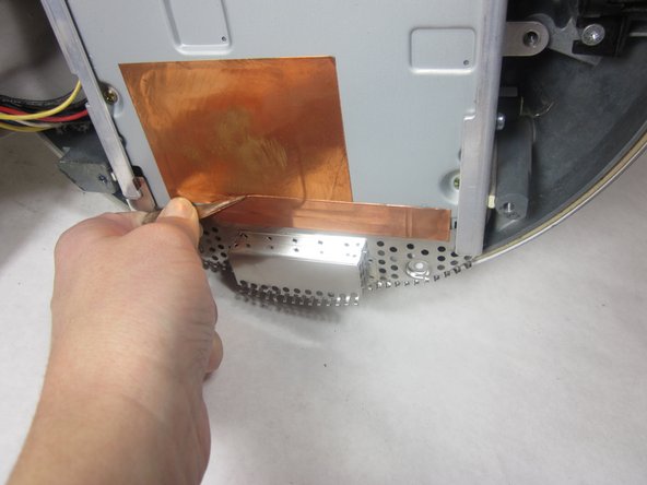
Carefully remove shield and copper tape
-
-
Cette étape n’est pas traduite. Aidez à la traduire
-
Remove the 4 10mm torx screws attatched to the drive carrier.
-
-
Cette étape n’est pas traduite. Aidez à la traduire
-
Grasp the carrier with both hands on each side.
-
Remove the carrier by lifting up and out.
-
-
Cette étape n’est pas traduite. Aidez à la traduire
-
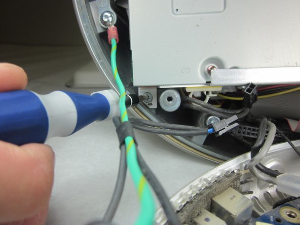
Flip the removed carrier to the right and pull out power cables.
-
-
Cette étape n’est pas traduite. Aidez à la traduire
-
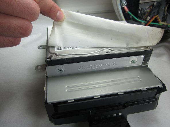
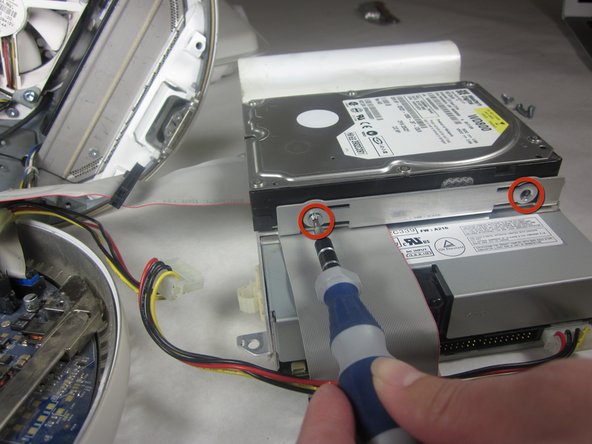
Peel back the white paper, revealing the screws that connect the hard drive to the carrier.
-
Remove the 4 T-10 5mm screws connecting the hard drive and frame. (There are 2 screws on each side)
-
-
Cette étape n’est pas traduite. Aidez à la traduire
-
Slide the hard drive out from the frame and optical drive.
-
-
Cette étape n’est pas traduite. Aidez à la traduire
-
Before you reassemble the computer, double check that your new hard drive has the same jumper configuration as the old one. This ensures the IDE "Master-Slave" protocol isn't interrupted. Some systems do not require this, but if you are having issues booting up afterwards with the storage or the disc drive, this could be the source of the problem.
-
-
Cette étape n’est pas traduite. Aidez à la traduire
-
Remove the four T-10 6mm screws at the sides of the drive.
-
-
Cette étape n’est pas traduite. Aidez à la traduire
-
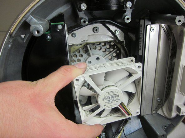
Take out the two T-15 screws that hold the fan brackets to the chassis.
-
Remove the four T-20 screws that hold the brackets onto the fan itself.
-
Now you can remove the fan from the computer. There may be an adhesive seal holding the fan to the chassis, so some force may be required.
-


Annulation : je n'ai pas terminé ce tutoriel.
6 autres ont terminé cette réparation.
Équipe

Cal Poly, Team 21-22, Maness Fall 2011 Membre de l'équipe Cal Poly, Team 21-22, Maness Fall 2011
CPSU-MANESS-F11S21G22
4 membres
13 tutoriels rédigés
6 commentaires
I don't see why it would be necessary... ??
anyone have a link for an adapter i can use to make any regular pc fan work in the imac g4? i was looking at a blue LED one on amazon and a guy said in the comments it would work but it needed an adapter but I can’t seem to find the correct one! plz help, thanks!
What size is the fan? Regular 3 pin connector?