Cette version peut contenir des modifications incorrectes. Passez au dernier aperçu vérifié.
Ce dont vous avez besoin
-
Cette étape n’est pas traduite. Aidez à la traduire
-
Remove the three T8 Torx screws securing the front bezel to the rear panel.
-
-
Cette étape n’est pas traduite. Aidez à la traduire
-
Use your thumbs to press both RAM arms in past the front bezel for enough clearance to lift it off the rear case.
-
-
Cette étape n’est pas traduite. Aidez à la traduire
-
While holding the RAM arms in with your thumbs, lift the lower edge of the front bezel enough to clear the rear case.
-
-
Cette étape n’est pas traduite. Aidez à la traduire
-
Insert a plastic card up into the corner of the air vent slot at the top of the rear case.
-
Push the card toward the top of the iMac to release the front bezel latch.
-
Pull the front bezel away from the rear case.
-
Repeat this process for the other side of the front bezel.
-
-
Cette étape n’est pas traduite. Aidez à la traduire
-
Lay your iMac stand-side down on a table.
-
Lift the front bezel from its lower edge and rotate it away from the rest of your iMac, minding the RAM arms that may get caught.
-
Lay the front bezel above the rest of the iMac.
-
-
Cette étape n’est pas traduite. Aidez à la traduire
-
If necessary, remove the piece of kapton tape wrapped around the microphone and camera cables.
-
-
-
Cette étape n’est pas traduite. Aidez à la traduire
-
Disconnect both the camera and microphone cables.
-
-
Cette étape n’est pas traduite. Aidez à la traduire
-
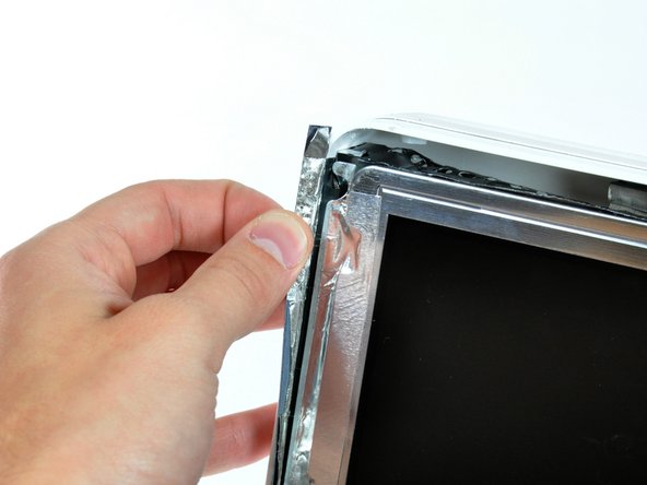
Peel back the aluminum EMI shield up off the lower three edges of the rear case.
-
-
Cette étape n’est pas traduite. Aidez à la traduire
-
Remove the two 5 mm T6 Torx screws securing the display data cable to the logic board.
-
Using its attached black tab, pull the display data cable connector up off the logic board.
-
-
Cette étape n’est pas traduite. Aidez à la traduire
-
Pull the inverter cable connector up off its socket on the logic board.
-
-
Cette étape n’est pas traduite. Aidez à la traduire
-
Peel back the aluminum EMI tape from the two vertical edges of the display.
-
-
Cette étape n’est pas traduite. Aidez à la traduire
-
Remove the four recessed coarse-thread 7.5 mm T10 Torx screws securing the display to the rear case.
-
-
Cette étape n’est pas traduite. Aidez à la traduire
-
Lift the display from its lower edge and pull it toward yourself to peel it off the EMI shield attached to its top edge.
-
-
Cette étape n’est pas traduite. Aidez à la traduire
-
Disconnect the hard drive thermal sensor by pulling the connector away from its socket parallel to the face of the hard drive.
-
-
Cette étape n’est pas traduite. Aidez à la traduire
-
Press the hard drive bracket down toward the bottom edge of your iMac to free it from the rear case, then rotate the top of the drive toward yourself.
-
Lift the hard drive off its lower pins and pull it out of the rear case, minding the cables that are still attached.
-
-
Cette étape n’est pas traduite. Aidez à la traduire
-
Insert the flat end of a spudger into the gap between the SATA power connector and the hard drive.
-
Twist the spudger to separate the SATA power connector from the hard drive.
-
Pull the SATA power connector away from the hard drive.
-
-
Cette étape n’est pas traduite. Aidez à la traduire
-
Pull the SATA data cable away from the hard drive.
-
Hard drive remains.
-
-
Cette étape n’est pas traduite. Aidez à la traduire
-
Pull the power supply cable connector away from its socket to disconnect it from the DC to DC board.
-
-
Cette étape n’est pas traduite. Aidez à la traduire
-
Use a pair of tweezers to pull the AC-in cable out from underneath the chassis.
-
-
Cette étape n’est pas traduite. Aidez à la traduire
-
Disconnect the AC-in cable by depressing the lock mechanism while pulling the connector away from its socket.
-
-
Cette étape n’est pas traduite. Aidez à la traduire
-
Remove the four T10 Torx screws securing the power supply to the rear case.
-
Lift the power supply out of the rear case, minding the AC-in cable that may get caught.
-


Annulation : je n'ai pas terminé ce tutoriel.
16 autres ont terminé cette réparation.
