Introduction
Dis-assembly of LCD panle to access the CCFL back lights assemblies.
Ce dont vous avez besoin
-
-
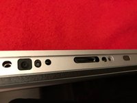
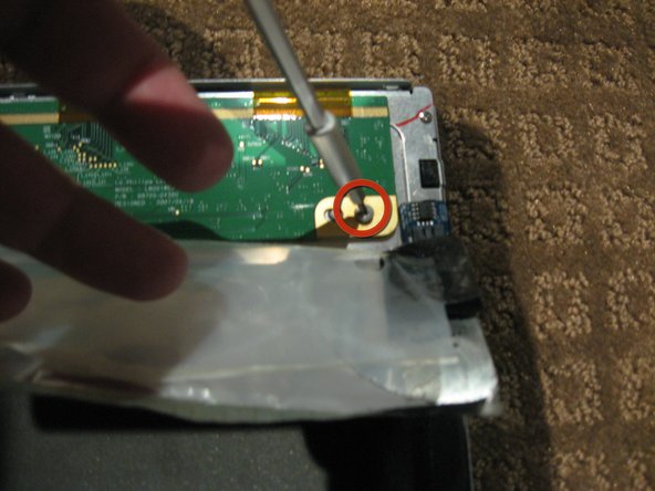
Loosen the single Phillips screw in the center of the access door.
-
Remove the access door from your iMac.
-
-
Outil utilisé dans cette étape :Heavy-Duty Suction Cups (Pair)$14.95
-
Stick two suction cups to opposing corners of the glass panel.
-
-
-
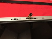
Remove the following 12 screws securing the front bezel to the rear case:
-
Eight 13 mm T8 Torx.
-
Four 25 mm T8 Torx.
-
-
-
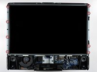
Place your hands at the top corners of the bezel (to the side) and lift the bezel 2-3cm from the body by working from the top. After this you can also disengage the bottom of the bezel (the memory modules will prevent the bottom of the bezel to detach first). When reassembling, start with the bottom of the bezel.
-
To fully detach the bezel: disconnect the microphone cable connector, removing tape as necessary.
-
To keep it attached, leave the microphone cable attached to the logic board, and place the bezel 'above' the chassis, with the microphone cable forming a hinge.
-
-
-
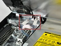
be sure to tuck the microphone cable and connector into the void next to the camera board.
-
Gently guide the microphone connector and cables through the ±1in long slot at the right of the iSight camera. Once the bezel is properly assembled, gently push the microphone connector and cable into the bezel through that slot.
-
-
-
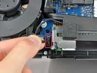
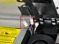
Pull the LCD temperature sensor connector straight up out of its socket on the logic board.
-
If necessary, de-route the LCD temperature sensor cable from behind the logic board.
-
-
-
-
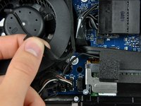
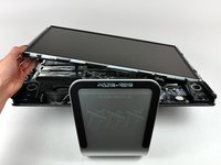
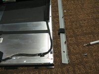
With the display panel still lifted, disconnect the four inverter cables.
-
If you are replacing a hard drive and have an extra set of hands, it is possible to reach in and remove the drive without disconnecting anything but the LCD temp and display connector in the previous step with the LCD in its propped position.
-
-
-
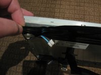
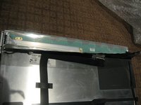
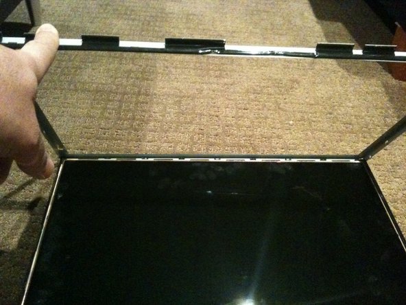
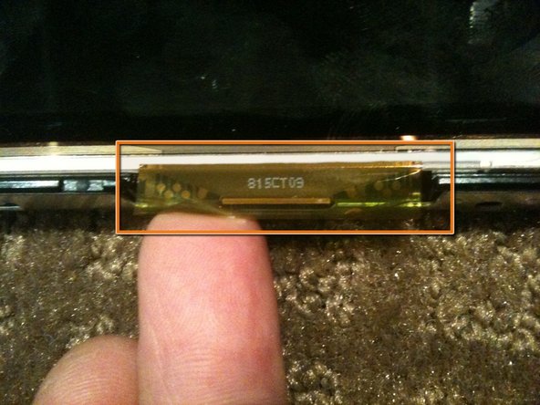
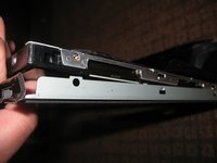
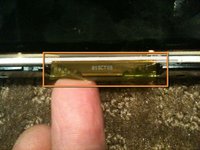
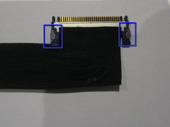
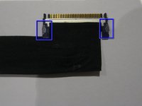
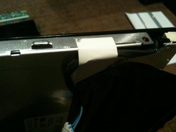
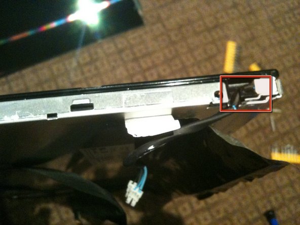
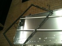
Once the LCD panel is removed you need to peel back the black foil from the top edge of the LCD to reveal the clear plastic PCB protector.
-
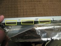
There are a total of 8 flex cables along the top edge
-
-
-
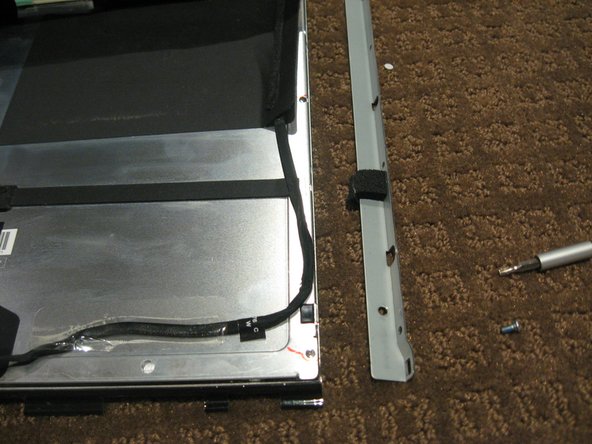
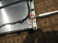
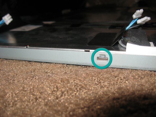
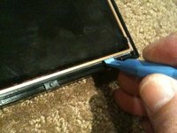
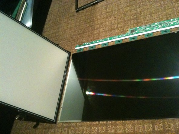
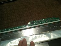
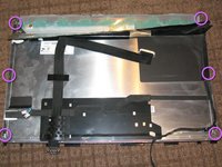
Stand the LCD panel on its TOP edge and locate the lock tabs along the BOTTOM edge. There are 5 along the length of the bottom edge
-
Use a flat blade driver or metal spudger to Gently pop the bezel off the lock tabs.
-
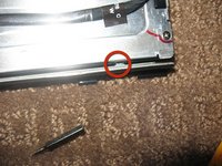
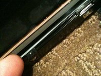
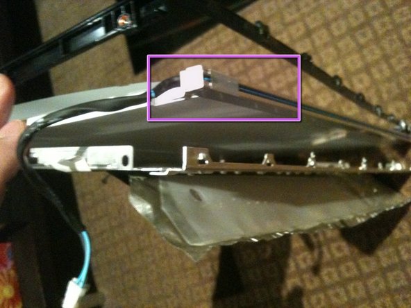
Locate the lock tabs on either side of the LCD panel. There are 2 on each side
-
Use a flat blade driver or metal spudger to Gently pop the bezel off the side lock tabs.
-
-
-
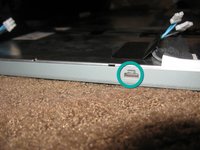
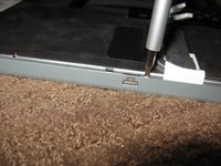
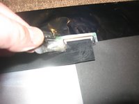
The bottom of the black surround can now be un-clipped and the entire surround removed
-
There are 4 tabs along the bottom of the assembly
-
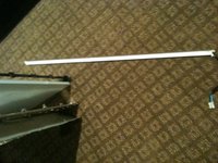
Once the black surround is off the rest pretty much comes apart with the bottom CCFL tube being able to be removed in a similar manner to the top
-
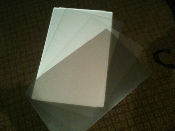
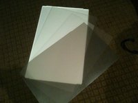
The centre of the back light assembly is made up of 4 main parts. A perspex sheet with white plastic coating, 2 opaque matt plastic sheets, and 1 Pearlescent matt plastic sheet
-
-
-
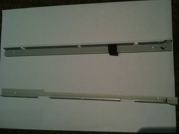
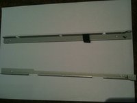
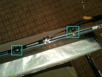
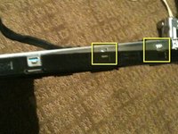
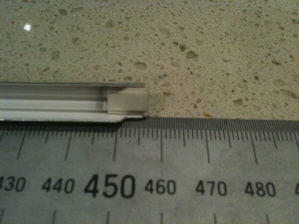
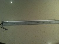
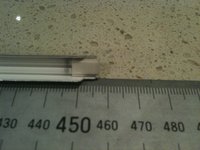
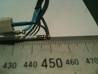
The CCLF tube assemblies are made up of a U shaped reflector with 2ea individual tubes inside. The entire assembly is 457mm long and 7.6mm wide. There are no part numbers on the assembly however there is a S on the end with the wires attached and an 18 on the other end.
-
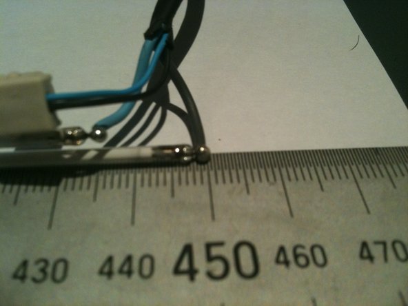
The individual tubes are 448mm long (excluding the terminals - standard way to measure is end of glass to end of glass) and are 2.4mm diameter.
-


To reassemble your device, follow these instructions in reverse order. (and pray!)
Reassembly takes more time as getting the CCFL back into place along the edge of the perspex sheet with the other layers all in place and flat is a bit of a challenge!
Annulation : je n'ai pas terminé ce tutoriel.
6 autres ont terminé cette réparation.

Équipe
