Cette version peut contenir des modifications incorrectes. Passez au dernier aperçu vérifié.
Ce dont vous avez besoin
-
Cette étape n’est pas traduite. Aidez à la traduire
-
If your display glass is cracked, keep further breakage contained and prevent bodily harm during your repair by taping the glass.
-
Lay overlapping strips of clear packing tape over the iPad's display until the whole face is covered.
-
Do your best to follow the rest of the guide as described. However, once the glass is broken, it will likely continue to crack as you work, and you may need to use a metal prying tool to scoop the glass out.
-
-
Cette étape n’est pas traduite. Aidez à la traduire
-
Insert a metal spudger between the right edge of the display assembly and the rear panel assembly.
-
Rotate the spudger away from you to release the tabs along the top edge of the display.
-
-
Cette étape n’est pas traduite. Aidez à la traduire
-
Insert a second metal spudger between the top edge of the display assembly and the rear panel assembly to keep the tabs from snapping back into place.
-
Pry the display assembly away from the rear panel.
-
-
Cette étape n’est pas traduite. Aidez à la traduire
-
Continue prying the display assembly away from the rear panel along the bottom and left edges of the iPad.
-
-
Cette étape n’est pas traduite. Aidez à la traduire
-
Lift the display assembly away from the rear panel assembly by its bottom edge.
-
-
Cette étape n’est pas traduite. Aidez à la traduire
-
Use the flat end of a spudger to pry the antenna connector closest to the bottom of the iPad up off its socket on the communications board.
-
-
Cette étape n’est pas traduite. Aidez à la traduire
-
In the following steps, you will disconnect the three cables attaching the display assembly to the logic board. The cables are for the following components:
-
Digitizer
-
Ambient Light Sensor
-
Display Data Cable
-
-
Cette étape n’est pas traduite. Aidez à la traduire
-
Use the edge of an iPod opening tool to flip up the retaining flaps holding the digitizer ribbon cables in their sockets on the logic board.
-
Pull the digitizer ribbon cables straight out of their sockets.
-
-
-
Cette étape n’est pas traduite. Aidez à la traduire
-
Use an iPod opening tool to remove the ambient light sensor connector from its socket by gently prying upward.
-
-
Cette étape n’est pas traduite. Aidez à la traduire
-
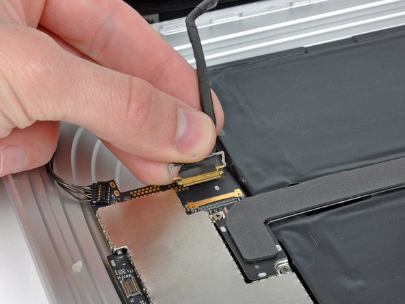
Disconnect the display data cable from the main board by flipping up the metal retainer by its black plastic pull tab.
-
Pull the cable connector away from its socket.
-
-
Cette étape n’est pas traduite. Aidez à la traduire
-
Remove the display assembly from the rear panel assembly.
-
-
Cette étape n’est pas traduite. Aidez à la traduire
-
Remove the two 4.56 mm T5 Torx screws securing the dock connector cable to the main board.
-
-
Cette étape n’est pas traduite. Aidez à la traduire
-
Remove the single 2.84 mm T5 Torx screw connecting the dock connector cable to the rear case assembly.
-
-
Cette étape n’est pas traduite. Aidez à la traduire
-
Remove the two 2.84 mm T5 Torx screws securing the dock connector cable to the rear panel assembly.
-
-
Cette étape n’est pas traduite. Aidez à la traduire
-
Carefully remove the plastic cover over the WiFi/Bluetooth board and dock connector cable using an iPod opening tool.
-
-
Cette étape n’est pas traduite. Aidez à la traduire
-
Pry the Wi-Fi and Bluetooth antennas up off their respective sockets on the Wi-Fi/Bluetooth board.
-
-
Cette étape n’est pas traduite. Aidez à la traduire
-
Remove the dock connector cable from the rear panel assembly.
-
-
Cette étape n’est pas traduite. Aidez à la traduire
-
Use the edge of an iPod opening tool to pry the SIM board connector up off it socket on the logic board.
-
-
Cette étape n’est pas traduite. Aidez à la traduire
-
Fold the SIM cable back for clearance to access the speaker connector.
-
Use the edge of an iPod opening tool to disconnect the speaker connector from the logic board.
-
-
Cette étape n’est pas traduite. Aidez à la traduire
-
Remove the two 2.84 mm T5 Torx screws securing the speaker assembly to the rear panel assembly.
-
-
Cette étape n’est pas traduite. Aidez à la traduire
-
De-route the Wi-Fi antenna through its channel in the speaker assembly.
-
-
Cette étape n’est pas traduite. Aidez à la traduire
-
Deroute the speaker cable connector from under the black sticker attached to the left side of the rear panel assembly.
-
-
Cette étape n’est pas traduite. Aidez à la traduire
-
Lift the speaker assembly and push it forward until the ports clear the bottom side of the rear panel assembly.
-


Annulation : je n'ai pas terminé ce tutoriel.
7 autres ont terminé cette réparation.
