Aller au contenu principal

Ce dont vous avez besoin

Cette vue éclatée n'est pas un tutoriel de réparation. Pour réparer votre BSP-D9, utilisez notre manuel de réparation.

  1. BSP-D9 Teardown, Opening the controller: étape 1, image 1 de 1
    • To open the controller there are 8 screws on the rear that need to be remove to access either side of the controller.

  2. BSP-D9 Teardown, Opening the left side: étape 2, image 1 de 2 BSP-D9 Teardown, Opening the left side: étape 2, image 2 de 2
    • We start with the left side as the battery is this side.

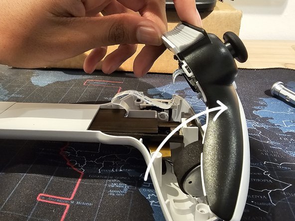
    • Start by squeezing the indicated area with your thumb

    • Then twist whilst pressing the squeezed area to open the controller to the left similarly to a book. As shown in the second image

  3. BSP-D9 Teardown, Disconnecting cables: étape 3, image 1 de 2 BSP-D9 Teardown, Disconnecting cables: étape 3, image 2 de 2
    • There are 4 connections hold the top piece in as labelled

    • 1. Rumble motor connection

    • 2. Macro Button connection

    • 3. Battery connection

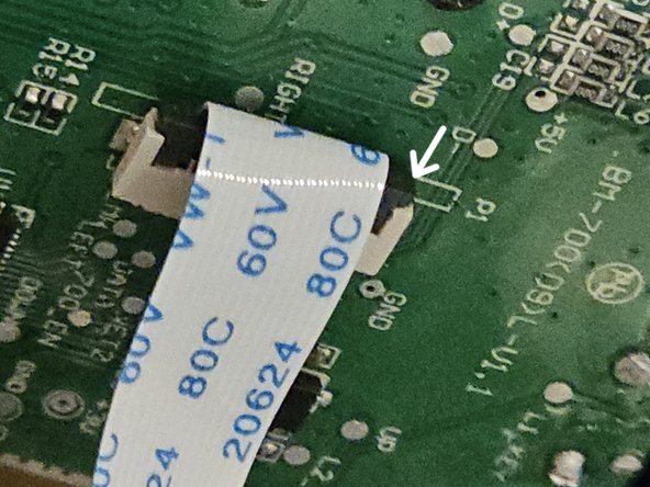
    • 4. Interconnect Flex Cable

    • Disconnect the battery first before disconnecting anything.

    • To disconnect the ZIF connector by picking on the grey bale. As shown

  4. BSP-D9 Teardown, Left Side PCB Removal: étape 4, image 1 de 1
    • In order to remove the PCB, unscrew the two screws as shown

  5. BSP-D9 Teardown, Left Side Toredown: étape 5, image 1 de 1
    • And with that the left side is tore down.

  6. BSP-D9 Teardown, Right Side Opening: étape 6, image 1 de 2 BSP-D9 Teardown, Right Side Opening: étape 6, image 2 de 2
    • Apply pressure in the region highlighted in the images.

    • After which twist the controller in the direction shown

  7. BSP-D9 Teardown, Right Side Cable Disconnect: étape 7, image 1 de 1
    • There are 3 connections for the right side.

    • 1. Interconnect Flex Cable Connector

    • 2. Rumble Motor Connector

    • 3. Macro button Connector

    • To disconnect the flex cable follow the same steps as the left side

  8. BSP-D9 Teardown, Removing the mainboard (R): étape 8, image 1 de 1
    • Remove the screws highlighted in the image

  9. BSP-D9 Teardown, Right Side Toredown: étape 9, image 1 de 1
    • That's the right side torn down.

Neville Davids

Membre depuis le 07/02/18

592 Réputation

3 tutoriels rédigés

0 commentaires

Ajouter un commentaire

Nombre de vues :

Dernières 24 heures : 11

7 derniers jours : 44

30 derniers jours : 229

Total : 229