Aller au contenu principal

Ce dont vous avez besoin

Cette vue éclatée n'est pas un tutoriel de réparation. Pour réparer votre Dell latitude 3500, utilisez notre manuel de réparation.

  1. Dell latitude 3500 Teardown, Remove bottom cover: étape 1, image 1 de 2 Dell latitude 3500 Teardown, Remove bottom cover: étape 1, image 2 de 2
    • 10 screws total

    • The screws don't come the whole way out of the cover, but you will feel when they are loosened enough.

    • A spudger will make quick work of removing the cover, but you may have to open the laptop to find a spot for it to fit.

    • Sometimes the cover can snag when you go to pull it off: a snap may have caught again, or a screw may be hanging on by a thread.

  2. Dell latitude 3500 Teardown, Remove Battery: étape 2, image 1 de 1
    • 4 screws total

    • Unplug it from the motherboard.

  3. Dell latitude 3500 Teardown, Remove RAM: étape 3, image 1 de 1
    • Carefully push the metal latches on each side of the module outwards.

  4. Dell latitude 3500 Teardown, Remove M.2 SSD: étape 4, image 1 de 3 Dell latitude 3500 Teardown, Remove M.2 SSD: étape 4, image 2 de 3 Dell latitude 3500 Teardown, Remove M.2 SSD: étape 4, image 3 de 3
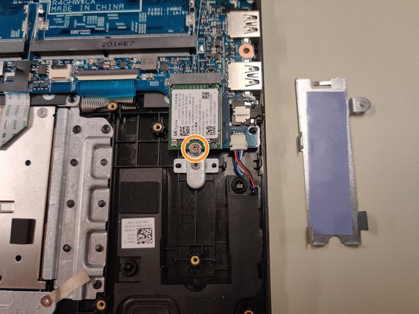
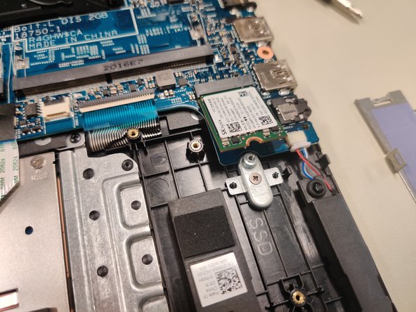
    • One screw holds an aluminum plate in place over the SSD to disperse heat.

    • Another screw holds the actual SSD in place.
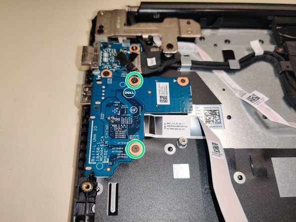
  5. Dell latitude 3500 Teardown, Remove USB/SD Card Reader: étape 5, image 1 de 3 Dell latitude 3500 Teardown, Remove USB/SD Card Reader: étape 5, image 2 de 3 Dell latitude 3500 Teardown, Remove USB/SD Card Reader: étape 5, image 3 de 3
    • 2 screws

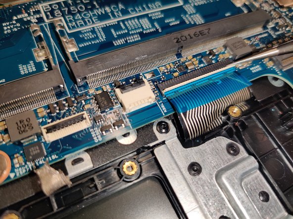
    • Carefully lift the black tab to free the ribbon cable from it's connection to the motherboard.

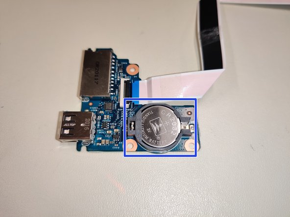
    • On the underside is where the CMOS battery is located.

  6. Dell latitude 3500 Teardown, Remove CPU Fan: étape 6, image 1 de 1
    • Unplug the small fan header from it's slot on the motherboard

    • 2 screws total holding the fan in place.
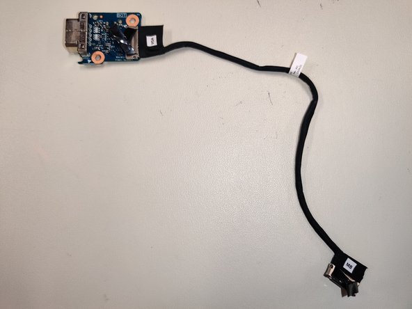
  7. Dell latitude 3500 Teardown, Remove VGA Board: étape 7, image 1 de 2 Dell latitude 3500 Teardown, Remove VGA Board: étape 7, image 2 de 2
    • 2 screws total

    • the cable can be unplugged from the motherboard by carefully pulling up on the connector

  8. Dell latitude 3500 Teardown, Remove Wi-Fi Card: étape 8, image 1 de 3 Dell latitude 3500 Teardown, Remove Wi-Fi Card: étape 8, image 2 de 3 Dell latitude 3500 Teardown, Remove Wi-Fi Card: étape 8, image 3 de 3
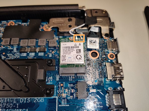
    • 1 screw total, holds a small bracket in place over the antennas.

    • Use a tool to carefully lift the antennas upwards from their connections.

  9. Dell latitude 3500 Teardown, Remove Touchpad: étape 9, image 1 de 1
    • There's a small amount of tape that needs peeled back

    • 7 screws total

    • There's also a small lip on the top edge of the touchpad that will catch if you pull it out at an angle.
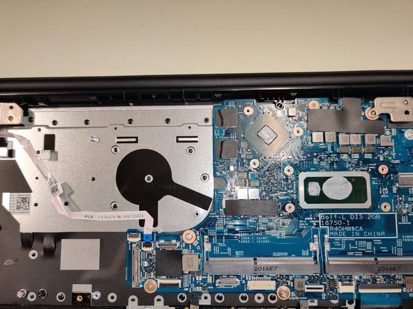
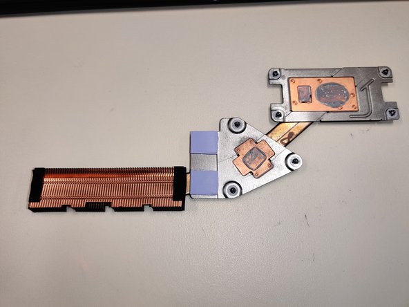
  10. Dell latitude 3500 Teardown, Remove CPU Heatsink: étape 10, image 1 de 3 Dell latitude 3500 Teardown, Remove CPU Heatsink: étape 10, image 2 de 3 Dell latitude 3500 Teardown, Remove CPU Heatsink: étape 10, image 3 de 3
    • 7 screws total

    • The screws are numbered to spread the thermal paste the most evenly across each die.

  11. Dell latitude 3500 Teardown, Lift Hinges: étape 11, image 1 de 2 Dell latitude 3500 Teardown, Lift Hinges: étape 11, image 2 de 2
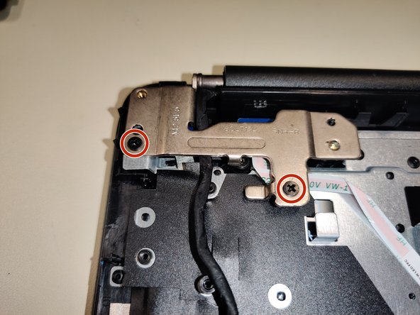
    • 2 screws on each side

    • These hinges hold the 2 halves together, so it will slide when you lift them up

  12. Dell latitude 3500 Teardown, Disconnect Remaining Connections: étape 12, image 1 de 1
    • There should be three connectors still attached to the motherboard.

  13. Dell latitude 3500 Teardown, Remove Motherboard: étape 13, image 1 de 3 Dell latitude 3500 Teardown, Remove Motherboard: étape 13, image 2 de 3 Dell latitude 3500 Teardown, Remove Motherboard: étape 13, image 3 de 3
    • 4 screws total

  14. Dell latitude 3500 Teardown, Remove Screen Cover: étape 14, image 1 de 3 Dell latitude 3500 Teardown, Remove Screen Cover: étape 14, image 2 de 3 Dell latitude 3500 Teardown, Remove Screen Cover: étape 14, image 3 de 3
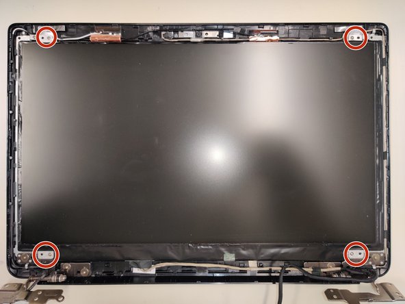
    • Spudge around the edges, even the hinge.

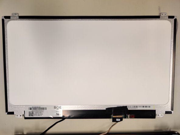
    • Thin(but strong) adhesive is placed around the border of the screen.

    • 4 screws holding screen in place.

Jake

Membre depuis le 03/08/23

1 300 Réputation

14 tutoriels rédigés

0 commentaires

Ajouter un commentaire

Nombre de vues :

Dernières 24 heures : 4

7 derniers jours : 10

30 derniers jours : 67

Total : 1,625