Introduction
The first laser printer teardown on iFixit.
Ce dont vous avez besoin
-
-
This teardown of the HP LaserJet 1320 is officially the first laser printer teardown on iFixit.
-
-
-
According to the service manual (there is a link in the documents section), the left cover of the printer can be opened without any tools by pulling on 2 tabs.
-
The service manual was right. For the record, this is actually easier than it sounds.
-
-
-
Now on to the formatter.
-
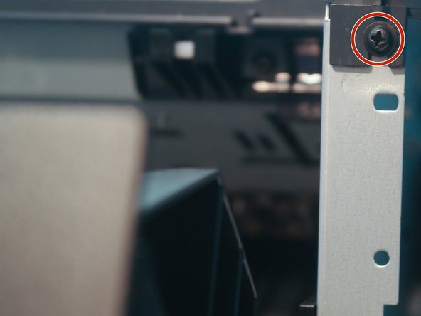
Remove 2 screws on the I/O port cover.
-
Remove 6 screws on the formatter cover.
-
Disconnect 3 connectors to the laser assembly, the cartridge connector, and the control panel.
-
Disconnect 2 flat flexible cables to the laser assembly and the control board.
-
-
-
Chips on the formatter:
-
PCA9551 I2C LED Blinker. I never knew there was a chip with the sole purpose of blinking LEDs.
-
STMicroelectronics E6V2HP
-
SC414445VF Proprietary ASIC
-
-
-
More chips on the formatter...
-
The large gray object on the right is a 100-pin DIMM slot for expanding the internal memory.
-
-
-
Removing the right cover is as easy as disengaging 3 tabs with the printer turned on its side.
-
-
-
The back cover can be removed by removing 4 screws on the back of the printer.
-
-
-
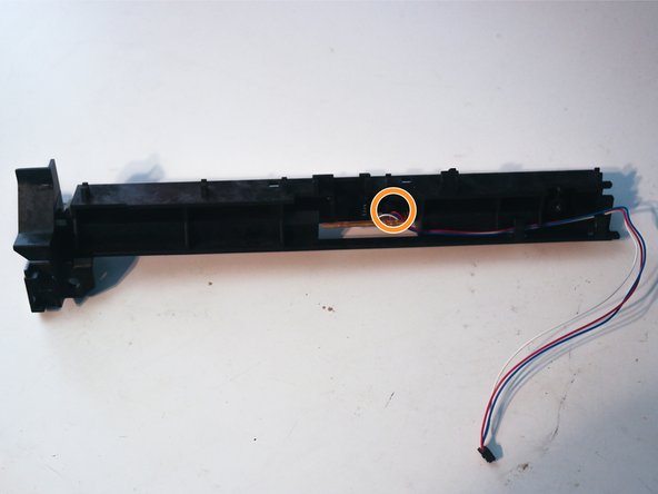
The duplexer tray can be removed by pulling outwards on the
bluegreenblue-green tab, which releases the magnets that hold the tray in place.
-
-
-
Remove 2 screws on the back of the printer, one on the left side, and one on the front.
-
-
-
After disconnecting the control panel cable, the top cover can be removed.
-
-
-
The control panel and its circuit board can easily be removed with a metal spudger.
-
-
-
Remove one cable from the laser assembly.
-
Remove 4 screws from the laser assembly.
-
-
-
Disconnect the fan cable from the control board on the back of the printer.
-
Remove the retaining clip from the fan.
-
Remove 2 screws holding in the fan.
-
While the fan can not be completely removed yet, this will make it easier to take apart other parts of the printer.
-
-
-
Remove 1 screw from the top of the cartridge connector.
-
Remove 1 screw on the front of the cartridge connector.
-
The cartridge connector can be removed from the printer.
-
-
-
The cable clip for the laser assembly cable can be removed from the chassis.
-
-
-
-
Remove 3 screws on the duplexer gear assembly.
-
The duplexer gearbox can now be removed.
-
Remove one screw holding down the duplexer solenoid.
-
This appears to be a standard 24V open-frame solenoid, although no markings were found on it.
-
-
-
Remove 3 screws to remove the safety interlock assembly.
-
Disconnect 2 spade connectors from the microswitch.
-
The safety interlock prevents the lasers or high-voltage power supply from being turned on when the cartridge door is open.
-
-
-
-
The fan cable can now be derouted from the cable guide and the fan can be removed.
-
-
-
Disconnect 2 cables from the control board.
-
Remove the gear from the fuser shaft.
-
Deroute the remaining cables in the cable guide.
-
-
-
Remove 4 screws to remove the main gear assembly.
-
Remove 1 screw to remove the third solenoid.
-
-
-
The cartridge door can be removed by removing 2 screws on the front of the printer.
-
-
-
The pickup roller can now be removed by rotating the white tabs upwards and pulling them out.
-
-
-
Remove 2 screws to remove the paper feed bar.
-
Remove 2 (hidden) screws to remove the registration assembly.
-
-
-
Disconnect the cable to the tray connector and route it through the hole in the chassis.
-
-
-
Disconnect 2 cables from the control board and remove them from the cable guide.
-
-
-
Remove the cable guide on the other side of the chassis.
-
Disconnect 2 connectors from the control board.
-
-
-
Deroute the tray connector cable through the cable guide.
-
Disconnect the main motor cable.
-
-
-
Remove 3 screws from the right side of the printer.
-
Remove 3 screws from the left side of the printer.
-
-
-
After removing the plastic clip, the soft foam pressure roller can be removed.
-
The metal rod in the roller allows the roller to be negatively charged, which prevents toner from sticking to the fusing film. Each end of the rod is coated in a conductive black liquid which helps it make contact with the high-voltage connector.
-
-
-
Remove 2 screws to remove the metal bar from the fuser.
-
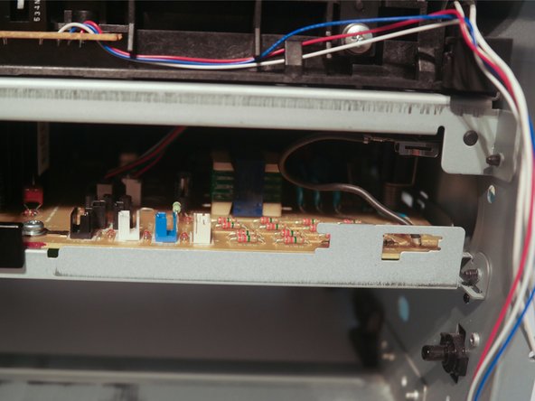
After removing one screw, this small circuit board can be removed.
-
The board contains a beam interrupt sensor, which contains an infrared LED pointing at an infrared phototransistor. When an object enters the slot and breaks the beam, the phototransistor detects it as a drop in infrared light.
-
-
-
Remove 4 screws on each side of the printer to remove the metal midframe piece that holds the chassis together.
-
The massive control board can now be seen.
-
-
-
Remove the tray connector and motor cables from the cable guide.
-
The high voltage corona wire used to apply a charge to the paper is visible in the right of these pictures (the spiked metal strip attached to the paper feed assembly)
-
-
-
Remove one screw holding down the tray connector cable guide and then remove the cable guide.
-
Remove one screw on the printer chassis.
-
-
-
Remove 2 screws from the left side of the chassis.
-
Push the safety interlock and formatter cables through the hole in the chassis.
-
-
-
Bend the chassis to allow the control board to come loose, and disconnect the 2 cables to the paper feed assembly to remove the control board.
-
-
-
Remove 4 screws on the control board to remove it from the metal plate.
-
-
-
Here are the major components on the top side of the control board:
-
CR8KM-12A Thyristor (Most likely for fuser control)
-
Unidentified high-voltage transformers
-
220uF 200V capacitor
-
Main switching transformer
-
-
-
Chips on the back of the board:
-
STMicroelectronics 324 E9SU518 - Possibly an LM324 Quad Op Amp?
-
STMicroelectronics 339 E9W2513 - Possibly an LM339 Quad Comparator?
-
Unidentified Texas Instruments chip with the part number sanded off.
-
Large QFP chip with the part number sanded off and a red and a blue mark on top.
-
Interestingly, all the chips were covered in a clear coating that made it hard to read the part numbers.
-
It appears that whoever designed this board was trying to prevent reverse engineering by making it hard to read the part numbers on the chips.
-
-
-
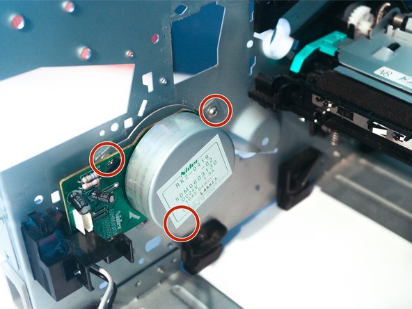
The main motor can be removed after unclipping the cable guide and removing 3 screws.
-
-
-
The motor is a Nidec RK2-0419, which appears to be appears to be a fairly powerful "outrunner" style brushless motor rated for 1.3A at 24V. The rotor (the round metal part) is about 3 inches in diameter and the entire motor weighs about 15 ounces.
-
This motor might be a special motor designed for use in this printer, as it and many other components have a number with the format RK2-0xxx on them.
-
The single chip on the motor is a BD6761FS Brushless Motor Driver.
-
-
-
This printer receives a perfect repairability score of 10/10.
-
No adhesives, thermoplastic staking, spot welding, or rivets are used.
-
Service manuals for this and most HP printers are easy to find and free.
-
Replacement parts are easy to find.
-
Printer is designed to be repaired.
-


Pièces jointes

6 commentaires
Looks like someone got a much longer teardown already :)
Excellent. I needed to see the polygon mirror of the LSU. It proved it’s too thin for my DIY project so you save me $12 for buying such unit from China
Hi Sir.
Sir, im facing both sides paper jam problem in hp 1320n printer.
Actually when the paper goes in the printer for printing the second side, at that time it blocks.
Kindly guide me.
Thanking you
The first thing I would do is strip it down to the level of the “duplex tray” as shown above, and inspect that, clean it and clean all the rollers with isopropyl alcohol. See if that helps!
Thanks for this teardown. It saved me hours resurrecting a printer I received as a gift. I’m impressed by the build quality of this printer. It’s like a brick outhouse, heaps of steel, and everything modular, with servicing in mind. Should last forever, since I can always fix it, thanks to you!!