Aller au contenu principal

Ce dont vous avez besoin

Cette vue éclatée n'est pas un tutoriel de réparation. Pour réparer votre Sony ICF-CD553RM Under Cabinet Kitchen CD Clock Radio, utilisez notre manuel de réparation.

  1. Sony ICF-CD553RM Under Cabinet Kitchen CD Clock Radio  Teardown, Removal of Top Cover Screws: étape 1, image 1 de 3 Sony ICF-CD553RM Under Cabinet Kitchen CD Clock Radio  Teardown, Removal of Top Cover Screws: étape 1, image 2 de 3 Sony ICF-CD553RM Under Cabinet Kitchen CD Clock Radio  Teardown, Removal of Top Cover Screws: étape 1, image 3 de 3
    • These are the only two tools that you will NEED for the duration of this tear down. It is NOT AT ALL NECESSARY to have an Allen wrench end, but a large and small screwdriver are required.

    • Unscrew the four mounting screws marked in GREEN, remove the respective PVC spacers from their places a well.

    • There are 22 SMALL SLIVER screws, all of the same length in each of the holes marked in RED. Remove each of these.

    • Lift the cover up until you experience resistance, then, with BOTH hands, gently wiggle the cover back until it is free.

  2. Sony ICF-CD553RM Under Cabinet Kitchen CD Clock Radio  Teardown, Removal of left Circut board and Speaker: étape 2, image 1 de 3 Sony ICF-CD553RM Under Cabinet Kitchen CD Clock Radio  Teardown, Removal of left Circut board and Speaker: étape 2, image 2 de 3 Sony ICF-CD553RM Under Cabinet Kitchen CD Clock Radio  Teardown, Removal of left Circut board and Speaker: étape 2, image 3 de 3
    • This is essentially what the inside should look like when you first remove the top cover.

    • Remove these 3 SMALL SILVER screws marked in GREEN. Once they are out, move the circuit board as much as possible to the side.

    • There are TINY WIRES connected EVERYWHERE. Be very CAUTIOUS of this, they may BREAK EASILY.

    • The Component marked in DARK BLUE is a rather LARGE capacitor. There are many others throughout this device as well.

    • Once the circuit board is out of the way, remove these 4 SMALL SILVER screws marked in RED and the respective metal braces under them from the 3W, 6Ω (Ohms) SONY speaker

    • When setting the speaker off to the side, be careful not to damage the fragile Diaphragm and Voice toll.

  3. Sony ICF-CD553RM Under Cabinet Kitchen CD Clock Radio  Teardown, Removal of Transformer: étape 3, image 1 de 3 Sony ICF-CD553RM Under Cabinet Kitchen CD Clock Radio  Teardown, Removal of Transformer: étape 3, image 2 de 3 Sony ICF-CD553RM Under Cabinet Kitchen CD Clock Radio  Teardown, Removal of Transformer: étape 3, image 3 de 3
    • Remove the 2 SMALL SILVER screws marked in GREEN. Once they are removed, set aside this Transformer-Circuit board.

    • The component marked in DARK BLUE is blowout fuse in case of a transformer overload.

    • As the circuit board states: "CAUTION FOR CONTINUED PROTECTION AGAINST FIRE, REPLACE ONLY WITH SAME TYPE SAME RATING FUSE. REFER TO SERVICE PERSONNEL."

    • The components marked in LAVENDER are Inductors

    • Note the LARGE WHITE main power cords' position after moving the transformer to the side, then also move the main power cord.

  4. Sony ICF-CD553RM Under Cabinet Kitchen CD Clock Radio  Teardown, Removal of Mother Board: étape 4, image 1 de 3 Sony ICF-CD553RM Under Cabinet Kitchen CD Clock Radio  Teardown, Removal of Mother Board: étape 4, image 2 de 3 Sony ICF-CD553RM Under Cabinet Kitchen CD Clock Radio  Teardown, Removal of Mother Board: étape 4, image 3 de 3
    • There are a lot of marker on this step, so pay close attention!

    • There are 7 SMALL BLACK screws marked in GREEN, Remove these.

    • There are 3 WHITE "RIBBON CABLES", marked i n RED and plugged into GREEN ports. Grab it the connection point and gently, but firmly pull up. It should disconnect smoothly and have blue plastic on the tip. This picture shows the Cables already removed.

    • There are 6 REMOVABLE wire bundle connection points, marked in ORANGE. 2 are RED, 4 are WHITE. Be VERY CAUTIOUS when disconnecting the wire bundles. DO NOT pull on the wires when trying to disconnect. Instead gently, but firmly pry the plastic connector glued to the wires, from the plastic connector secured to the board.

    • There is one long, unmarked wire bundle connector that is irremovable. This is purposed for keeping the motherboard permanently attached to the main circuit.

    • On the reverse side of the motherboard, there are 3 microprocessors marked in DARK BLUE.

  5. Sony ICF-CD553RM Under Cabinet Kitchen CD Clock Radio  Teardown, Removing the Disk Reader: étape 5, image 1 de 3 Sony ICF-CD553RM Under Cabinet Kitchen CD Clock Radio  Teardown, Removing the Disk Reader: étape 5, image 2 de 3 Sony ICF-CD553RM Under Cabinet Kitchen CD Clock Radio  Teardown, Removing the Disk Reader: étape 5, image 3 de 3
    • If you would rather move onto an easier section not involving the Disk Reader, then please move onto STEP 6.

    • Pull the disk slot out through the front end.

    • There are 2 VERY SMALL SILVER screws marked in GREEN. Remove them.

    • Using 1 or 2 hands, pull the silver end from the black part of the disk slot.

    • CAUTION! Make sure you don't touch the LED (Light Emitting Diode) disk reading laser light marked in RED. It can be easily damaged and with a touch, may be rendered unusable.

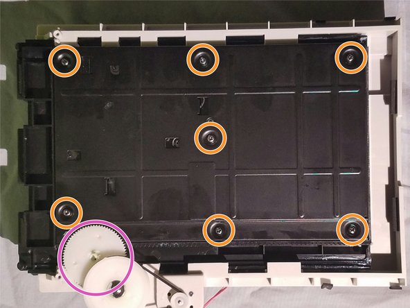
    • Once the silver part is off, push the disk slot back into the reader and slip the entire grey topped unit up and back out of the main body. Now flip the unit over to the black side and remove the 7 SMALL BLACK SCREWS marked in ORANGE

    • Now to remove the black plate, the gear marked in purple inhibits this, but pulling the slot outwards and wiggling/ GENTLY raising the gear a little will allow you the leverage to remove the plate.

    • There are 5 SMALL BLACK screws marked in YELLOW. Remove them.

  6. Sony ICF-CD553RM Under Cabinet Kitchen CD Clock Radio  Teardown, Removing the Right Circuit board and Speaker: étape 6, image 1 de 3 Sony ICF-CD553RM Under Cabinet Kitchen CD Clock Radio  Teardown, Removing the Right Circuit board and Speaker: étape 6, image 2 de 3 Sony ICF-CD553RM Under Cabinet Kitchen CD Clock Radio  Teardown, Removing the Right Circuit board and Speaker: étape 6, image 3 de 3
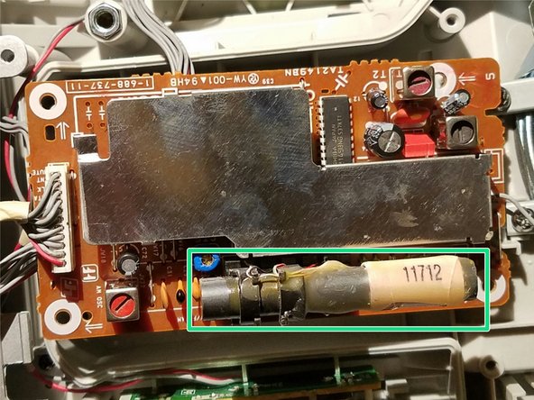
    • Remove the 4 SMALL SILVER screws. Flip the circuit board over.

    • Before you flip, the arrow in DARK BLUE marks the protective plating, this suggests there are some particularly fragile components in this circuit board.

    • The component marked in GREEN is the tuner for the AM radio.

    • Now, move the circuit board out of the way and remove these 4 SMALL SILVER screws marked in Orange and the respective metal braces under them from the 3W, 6Ω (Ohms) SONY speaker

    • When setting the speaker off to the side, be careful not to damage the fragile Diaphragm and Voice toll.

  7. Sony ICF-CD553RM Under Cabinet Kitchen CD Clock Radio  Teardown, Removing the Side Panel Circuit Board: étape 7, image 1 de 2 Sony ICF-CD553RM Under Cabinet Kitchen CD Clock Radio  Teardown, Removing the Side Panel Circuit Board: étape 7, image 2 de 2
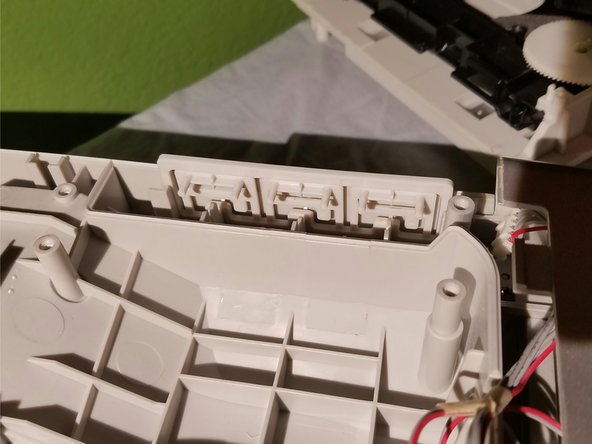
    • Lift up the green circuit board on the right side of the main body and set it to the side.

    • Now lift up the grey frame positioned directly behind the circuit board and set it to the side.

  8. Sony ICF-CD553RM Under Cabinet Kitchen CD Clock Radio  Teardown, Removal of the Face: étape 8, image 1 de 3 Sony ICF-CD553RM Under Cabinet Kitchen CD Clock Radio  Teardown, Removal of the Face: étape 8, image 2 de 3 Sony ICF-CD553RM Under Cabinet Kitchen CD Clock Radio  Teardown, Removal of the Face: étape 8, image 3 de 3
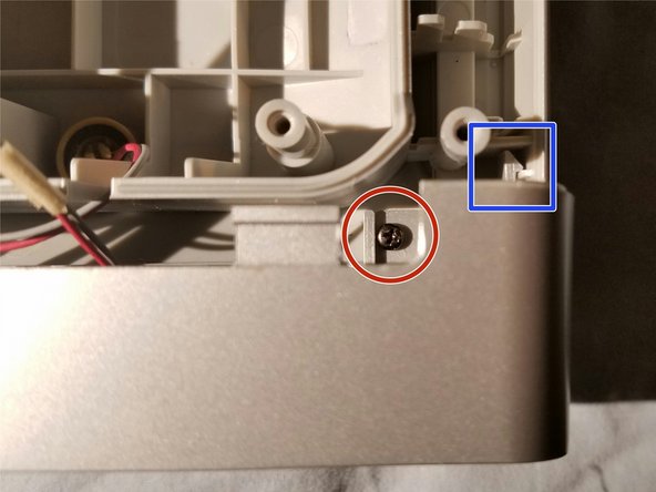
    • Remove the 1 SMALL BLACK screw marked in GREEN on the LEFT front side.

    • Remove the 1 SMALL BLACK screw marked in RED on the RIGHT front side.

    • Remove the 2 SMALL BLACK screws marked in ORANGE.

    • Note the mechanisms marked in DARK BLUE on both sides but shown on the RIGHT side only. They will put up resistance when wiggling the face off.

  9. Sony ICF-CD553RM Under Cabinet Kitchen CD Clock Radio  Teardown, Disassembling the face: étape 9, image 1 de 3 Sony ICF-CD553RM Under Cabinet Kitchen CD Clock Radio  Teardown, Disassembling the face: étape 9, image 2 de 3 Sony ICF-CD553RM Under Cabinet Kitchen CD Clock Radio  Teardown, Disassembling the face: étape 9, image 3 de 3
    • Remove the 7 VERY SMALL SILVER screws marked in RED.

    • Remove the 3 VERY SMALL SILVER screws marked in ORANGE.

    • LCD screen component: black part marked in GREEN; attached to main dial.

Aidan White

Membre depuis le 10/25/16

101 Réputation

1 tutoriel rédigé

Un commentaire

Can I wire exterior speakers into my under mount cabinet CD player ?? I can’t believe I haven’t found anything online about this

Hotrod Roxie - Réponse

Ajouter un commentaire

Nombre de vues :

Dernières 24 heures : 0

7 derniers jours : 1

30 derniers jours : 15

Total : 2,201