Ce dont vous avez besoin
Outils


-
-
-
une vis cruciforme PH1 située à l'arrière pour retirer le cache de batterie
 Demander à FixBot
-
-
-
Trois vis Tri-point Y0 sont situées sous le cache de la batterie
-
Ensuite, la façade rouge/blanche sort par l'avant
-
-
-
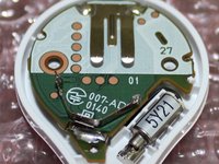
Le circuit imprimé est posé sur trois supports en plastique et n'est maintenu en place que par la pression des vis arrière.
-
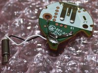
Le circuit imprimé et le moteur à vibration peuvent être retirés en exerçant une très légère pression.
-
-
-
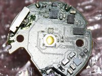
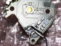
Bouton de fonction situé au centre
-
Voyant LED multicolore à côté du bouton
-
-
-
-
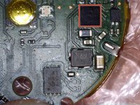
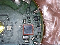
Processeur intégré Dialog Semiconductors DA14580
-
-









18 commentaires de tutoriel
This post needs moar wisdom
Anybody able to spot a Pedometer?
There is no pedometer. It's just a Bluetooth clicker. Your phone's sensors track all movement.
What is the
"A1
HNG
SBJ"
chip in "step 6"?
I2C/SPI flash?
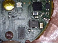
And.. what is in "Step 4" the chip? in between the capacitors and that "mostlikely MOSFETs for driving LEDs".
I'm looking at DA14580 modules on ebay:
http://www.ebay.com/sch/i.html?_from=R40...
And I tend to to say "let's try to clone this", the DA14580 has OTA programmable FLASH. :)
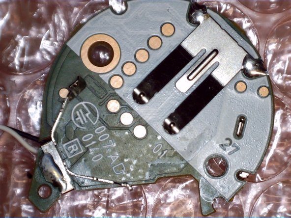
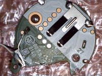
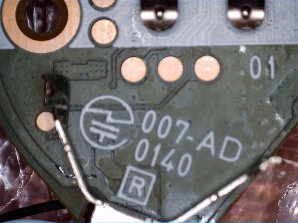
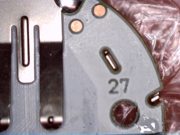
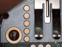
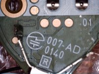
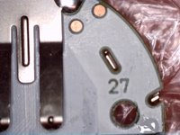
Last picture is most likely JTAG pogo contact points. For programming and testing. The board seems to be like 3-4+ layer board just based on the pictures. Also can't really tell you what chips those are with that quality of a picture. However the two little chips under the mounting hole on the picture in step 4 looks to be the DC Boost IC to keep constant voltage throughout the batteries life. The chip to the left of those boost converts is most likely the Bluetooth IC (just guessing by the location and the traces around it). Hope this helps :)
