Introduction
This is a prerequisite-only guide! This guide is part of another procedure and is not meant to be used alone.
Follow this guide to disconnect the battery on a HTC Vive Focus.
Power down your device before you begin. Be careful not to power on your device while making repairs. If you accidentally power on your device, stop working and power it back off before you resume.
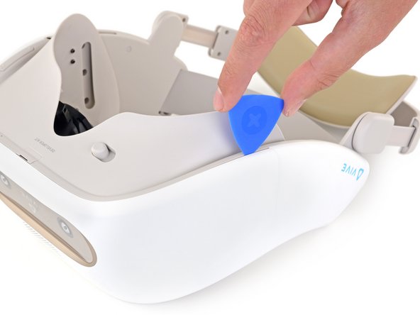
This repair requires breaking the plastic welds that help secure the front cover to the device. If you complete this repair, the gaps between the plastic front cover and side panels will no longer be flush. This damage is permanent but only cosmetic and will not affect the device’s functionality, usability, or operation.
Ce dont vous avez besoin
-
-
Place your device upside-down on your work surface.
-
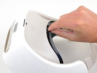
Use your fingers to gently pull the facerest cushion straight off of the facerest to remove it.
-
-
-
Use a T5 Torx screwdriver to remove the eight 4.5 mm screws securing the facerest.
-
-
-
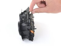
Carefully flip your device over.
-
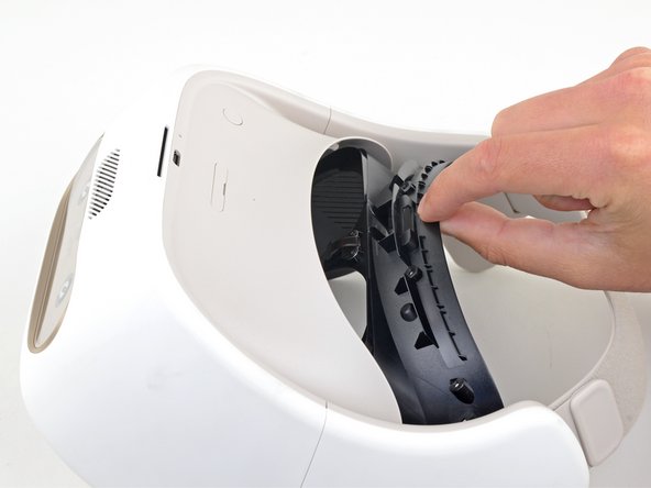
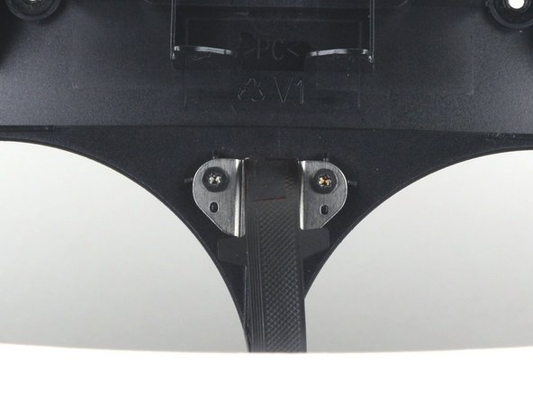
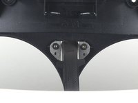
Pull the facerest out just enough to access the screws securing the facerest sensor.
-
-
-
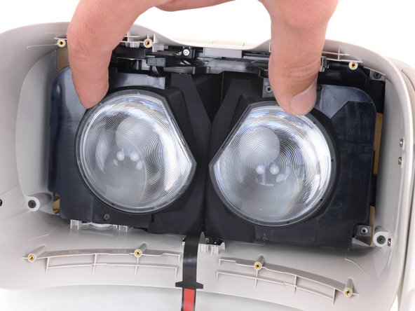
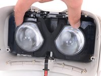
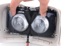
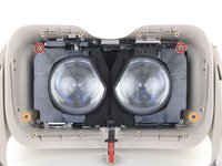
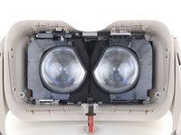
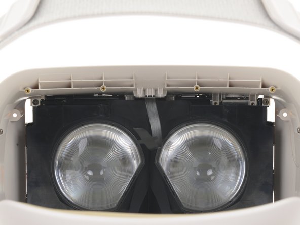
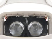
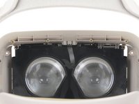
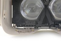
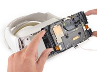
Use your fingers to slide the lenses towards each other so that they are positioned towards the center of the device.
-
-
-
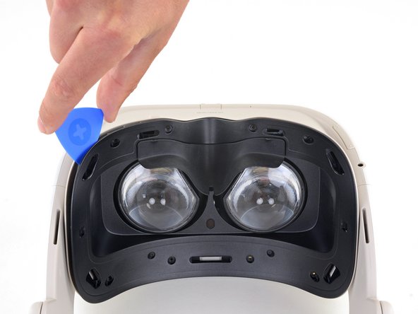
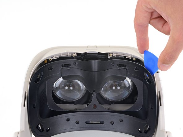
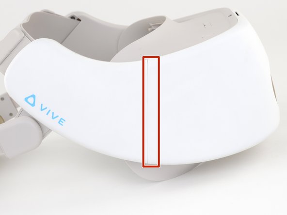
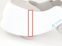
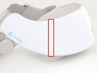
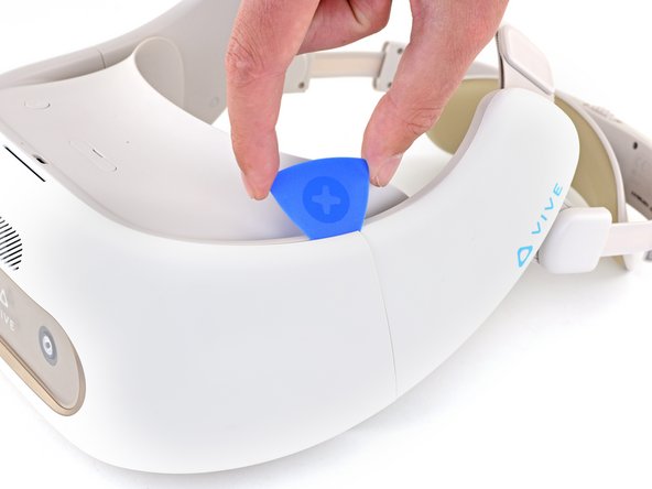
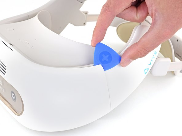
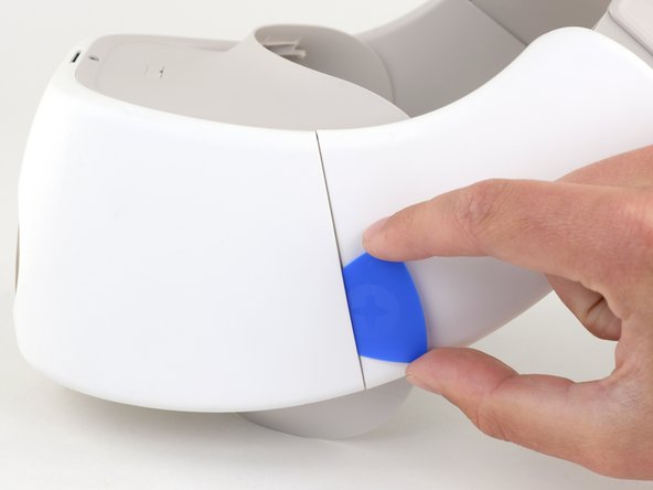
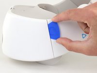
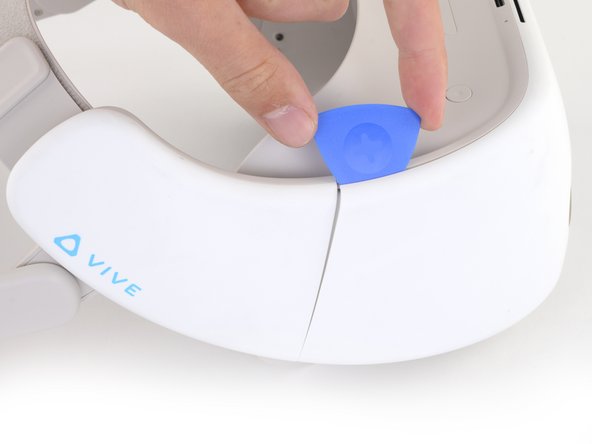
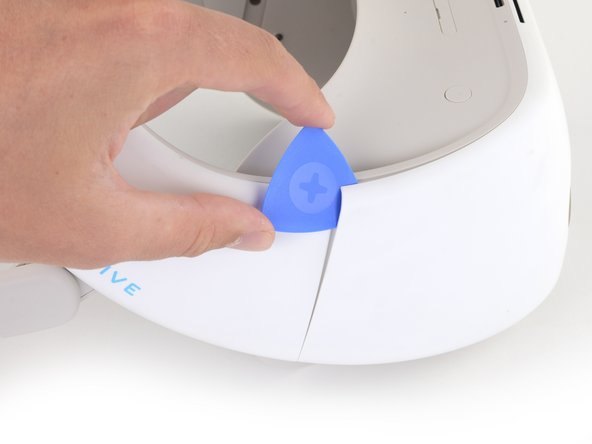
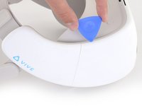
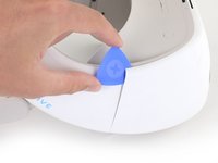
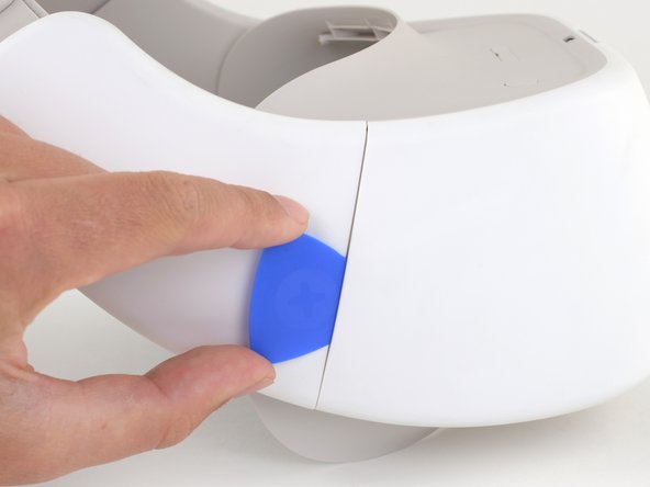
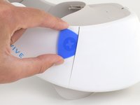
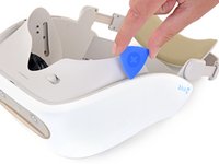
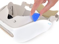
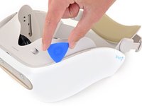
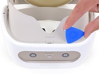
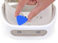
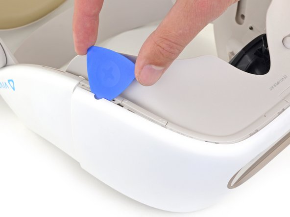
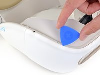
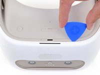
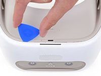
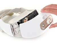
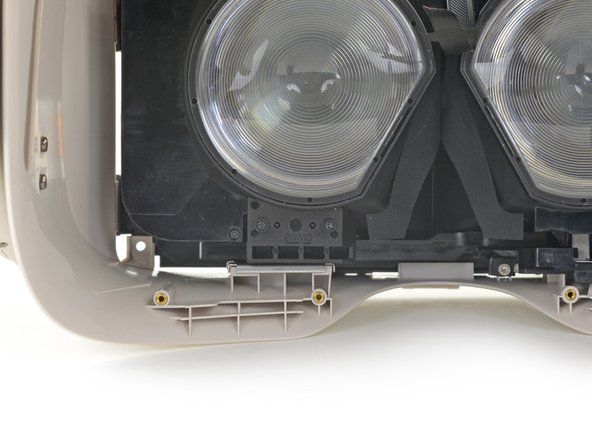
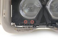
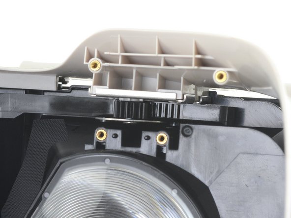
Note the location of the plastic welds on both vertical edges of the front cover.
-
-
-
Outil utilisé dans cette étape :Tweezers$3.99
-
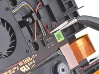
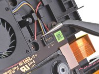
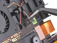
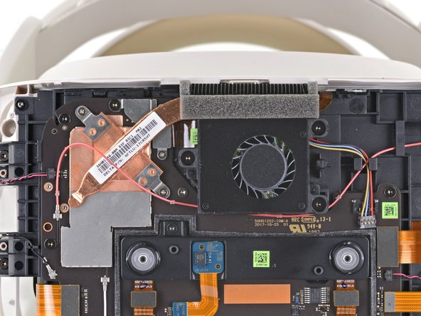
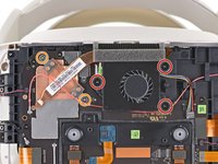
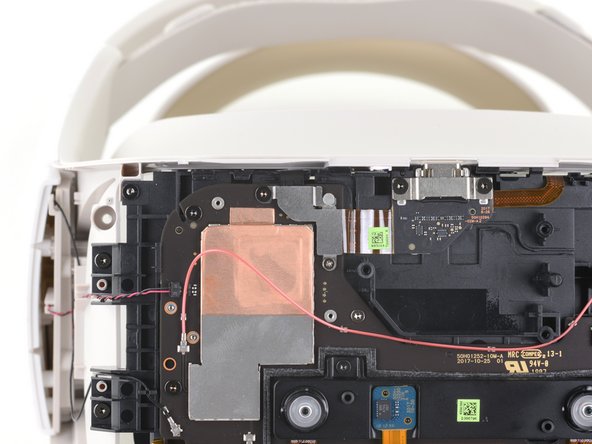
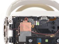
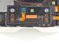
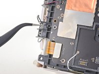
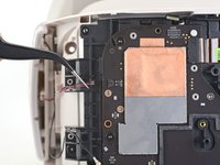
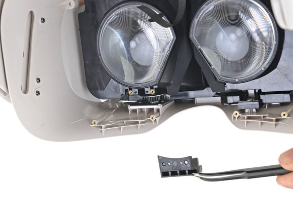
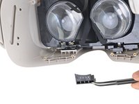
Use a pair of angled tweezers to disconnect the CPU fan cable from the motherboard.
-
-
-
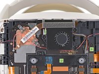
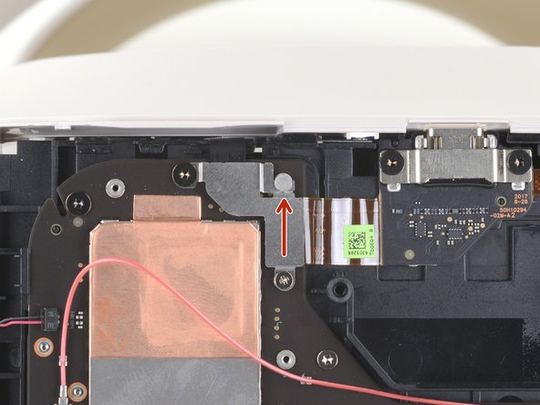
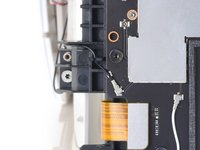
Use a T5 Torx screwdriver to remove the black 5.5 mm screw from the power button cable bracket.
-
Use a Phillips screwdriver to remove the 2.3 mm screw from the power button cable bracket.
-
-
-
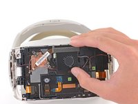
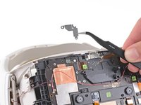
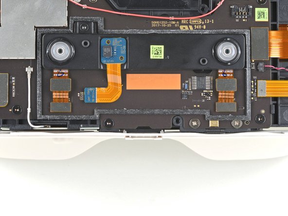
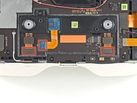
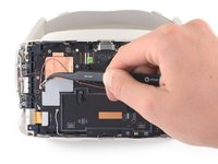
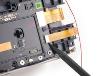
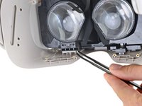
Pry up with the flat end of a spudger to disconnect the three ribbon cables connecting the proximity sensor array to the motherboard.
-
-
-
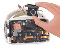
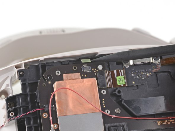
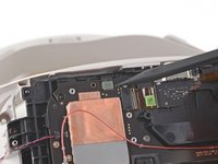
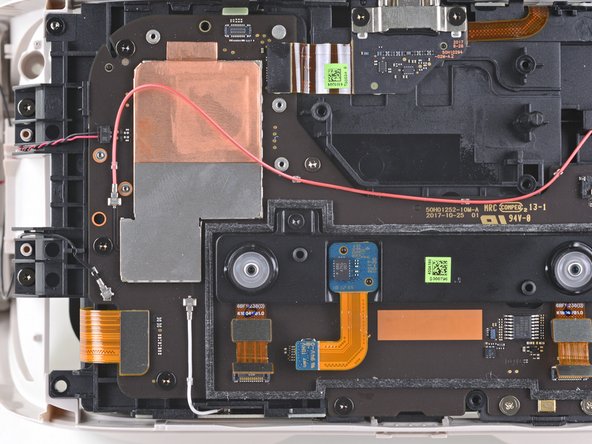
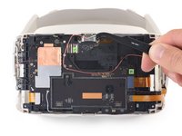
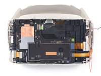
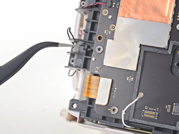
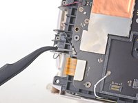
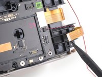
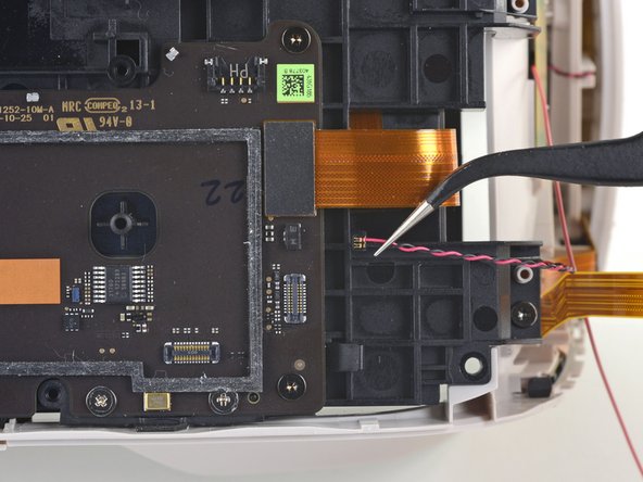
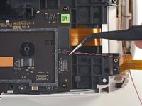
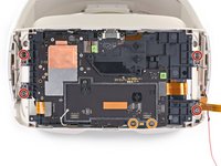
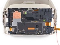
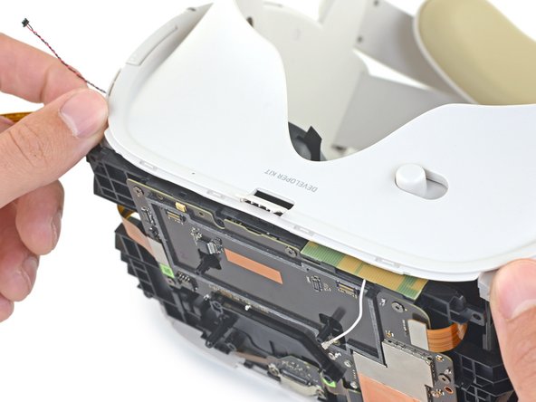
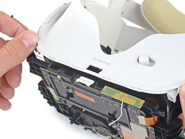
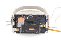
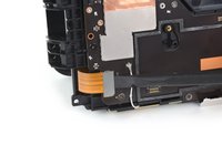
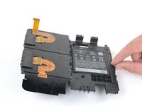
Use a spudger or a pair of tweezers to disconnect the red antenna cable from the front of the device.
-
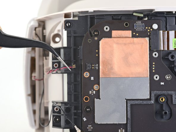
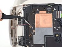
De-route the antenna cable from the front of the device and place it to the side.
-
-
-
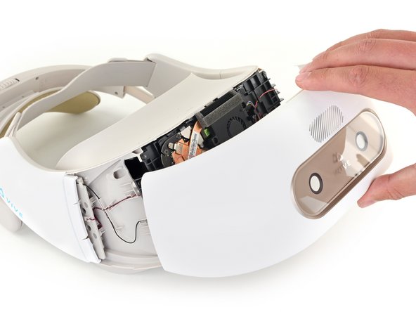
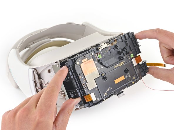
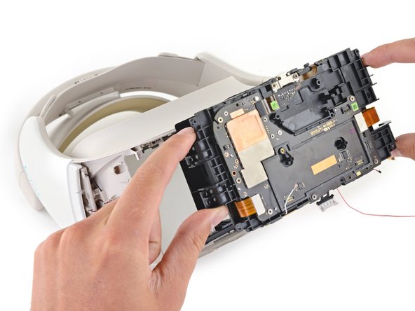
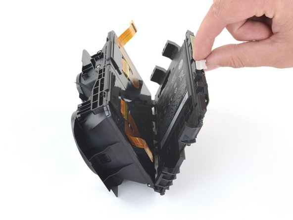
Make sure not to trap any of the five loose wires and cables when reinstalling the internal assembly.
-
Hold the lenses as close together as possible and align the rack and pinion with the gear and washer.
-
-
-
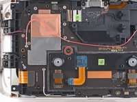
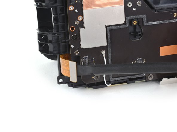
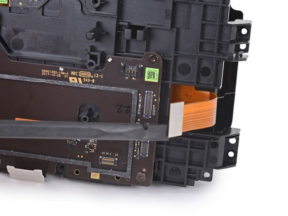
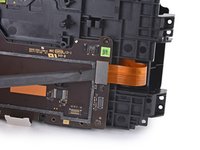
Use the flat end of a spudger to disconnect the left LED display ribbon cable from the motherboard.
-
-
-
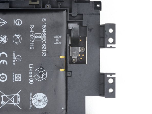
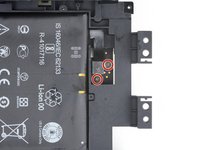
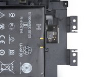
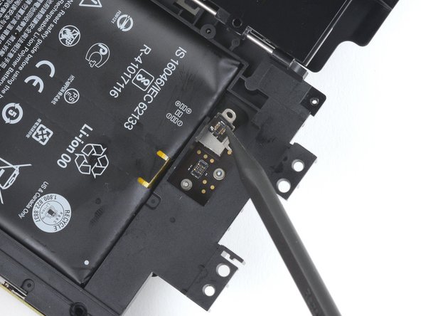
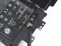
Use a Phillips screwdriver to remove the two 2.3 mm screws securing the battery cable to the back of the motherboard.
-


To reassemble your device, follow the above steps in reverse order.
Repair didn’t go as planned? Try some basic troubleshooting, or ask our Answers community for help.
