Cette version peut contenir des modifications incorrectes. Passez au dernier aperçu vérifié.
Ce dont vous avez besoin
-
Cette étape n’est pas traduite. Aidez à la traduire
-
Use your fingernail to slide the dark gray tab located on the bottom of the device towards the edge of camera.
-
Slide the light gray door away from the LCD screen and pull up to open the door.
-
-
Cette étape n’est pas traduite. Aidez à la traduire
-
Rotate the small brown tab towards the edge of the camera.
-
The battery should pop up.
-
-
Cette étape n’est pas traduite. Aidez à la traduire
-
Pull the battery straight out of the battery holder.
-
-
Cette étape n’est pas traduite. Aidez à la traduire
-
Close the light gray battery compartment door.
-
Remove the six 2.8 mm Phillips screws on the outside of the case. Two screws are found on each side of the camera, and the final two are found on the bottom.
-
-
Cette étape n’est pas traduite. Aidez à la traduire
-
Use your fingers to carefully pry off the back casing from the camera assembly.
-
-
Cette étape n’est pas traduite. Aidez à la traduire
-
Push the buttons out with your finger if they did not fall out while removing the casing.
-
Pull off the white plastic side piece if it did not fall out while removing the casing.
-
-
Cette étape n’est pas traduite. Aidez à la traduire
-
Remove the one 2.2 mm Phillips screw from the bottom of the camera.
-
Take off the print button.
-
-
Cette étape n’est pas traduite. Aidez à la traduire
-
Use your fingers to carefully pry off the front casing of the camera. The front casing should pull straight off.
-
-
Cette étape n’est pas traduite. Aidez à la traduire
-
Use the flat end of the spudger to lift open the white plastic latch on the front of the camera. Once the latch is lifted up, move the latch up towards the top edge of the camera.
-
Remove the top button assembly by pulling straight up.
-
-
Cette étape n’est pas traduite. Aidez à la traduire
-
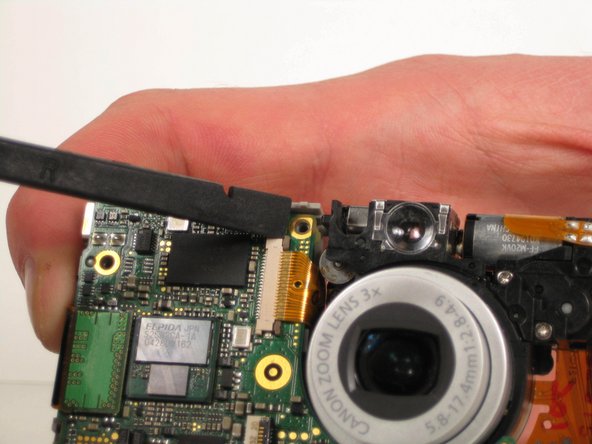
Remove the one 2.4 mm Phillips screw from the bottom of the motherboard.
-
Remove the two 3.9 mm Phillips screws from the top of the motherboard.
-
-
-
Cette étape n’est pas traduite. Aidez à la traduire
-
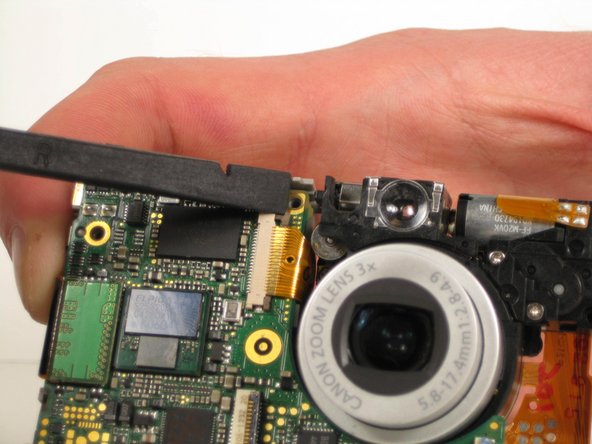
Remove the one 2.4 mm Phillips screw directly above the top right corner of the LCD screen.
-
-
Cette étape n’est pas traduite. Aidez à la traduire
-
Use the flat end of the spudger to lift up the small black connector from the back side of the motherboard. The connector should just lift straight up.
-
-
Cette étape n’est pas traduite. Aidez à la traduire
-
Hold the camera at an angle to locate the small blue ZIF connector on the back side of the motherboard and next to the LCD screen.
-
Use the flat end of the spudger to flip up the tab of the blue ZIF connector. Slide the ribbon cable out.
-
-
Cette étape n’est pas traduite. Aidez à la traduire
-
Remove the four 2.6 mm Phillips screws located underneath where the LCD screen used to be.
-
Remove the one 4.2 mm Phillips screw from the bottom of the back face of the camera.
-
-
Cette étape n’est pas traduite. Aidez à la traduire
-
Remove the one 2.7 mm Phillips screw from the left side of the camera.
-
-
Cette étape n’est pas traduite. Aidez à la traduire
-
Using the flat end of the spudger, begin to slightly peel back the orange ribbon cable from the rest of the camera by lifting up at the bottom corner. The ribbon cable should pop off of the pegs.
-
Rotate the speaker so that it unlatches from the camera frame. Then use the flat end of the spudger to lift up the speaker from the rest of the camera.
-
-
Cette étape n’est pas traduite. Aidez à la traduire
-
Use the flat end of the spudger to peel back the orange ribbon cable on the top of the camera where the power button contact is located. Only apply enough force to lift the power button contact up from the rest of the camera.
-
Use the flat end of the spudger to lift up the LED bulb from the rest of the camera.
-
-
Cette étape n’est pas traduite. Aidez à la traduire
-
Rotate the camera upside down to locate the small black ZIF connector located in the middle of the camera.
-
Use the flat end of the spudger to flip up the tab on the black ZIF connector. Pull the ribbon cable straight out.
-
Remove the orange ribbon cable from the rest of the camera.
-
-
Cette étape n’est pas traduite. Aidez à la traduire
-
Remove the one 4.3 mm Phillips screw that is now visible, which is located at the top right of the back of the camera.
-
-
Cette étape n’est pas traduite. Aidez à la traduire
-
Locate the two ZIF connectors on the front of the camera.
-
Use the flat end of the spudger to flip up the tab on the blue ZIF connector. Then pull the ribbon cable straight out.
-
-
Cette étape n’est pas traduite. Aidez à la traduire
-
Lay the camera on its front side.
-
Hold down on the camera's metal casing with one hand. Using your other hand, lift the LCD screen straight up, making sure the LCD screen's ribbon cable slides free of metal casing.
-
-
Cette étape n’est pas traduite. Aidez à la traduire
-
Use your fingers to carefully pry off the back metal casing.
-
Separate the metal case and tripod internal thread end from the rest of the camera.
-
-
Cette étape n’est pas traduite. Aidez à la traduire
-
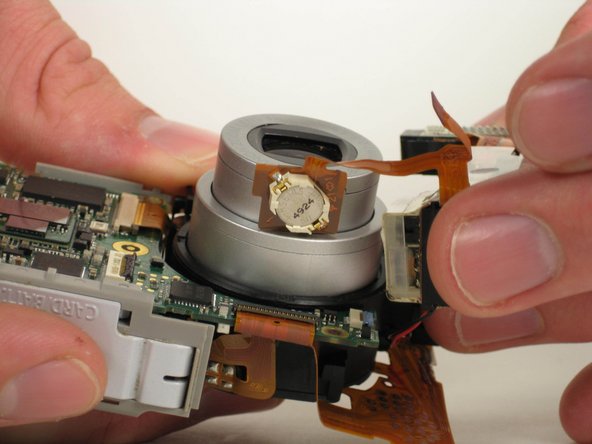
Lift flash assembly up.
-
Rotate flash assembly away from the camera.
-
-
Cette étape n’est pas traduite. Aidez à la traduire
-
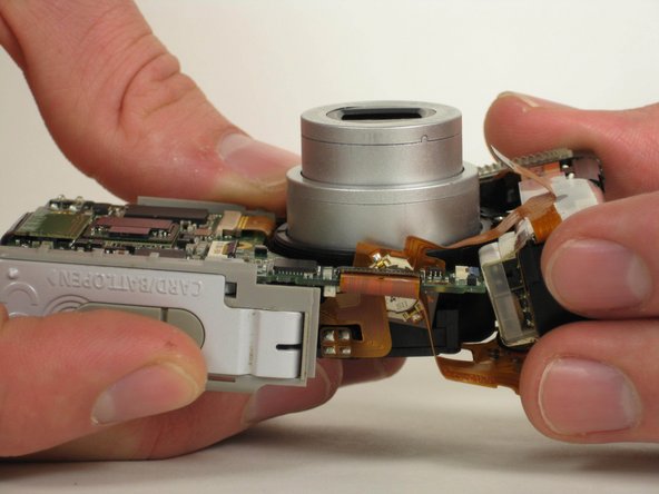
Use your fingers to give a small gap of space between the bottom of the lens assembly and the motherboard.
-
Slide the small circular battery, which is part of the flash assembly, through the small gap.
-
Separate the flash assembly from the rest of the camera.
-
-
Cette étape n’est pas traduite. Aidez à la traduire
-
Locate the black ZIF connector located directly below the lens.
-
Use the flat end of the spudger to flip up the black tab on the ZIF connector and pull the ribbon cable straight out.
-
-
Cette étape n’est pas traduite. Aidez à la traduire
-
Locate the brown ZIF connector located on the front of the camera.
-
Use the flat end of the spudger to push the small top brown tab out towards the lens. Repeat for the bottom brown tab.
-
Pull the ribbon cable out from the ZIF connector.
-
-
Cette étape n’est pas traduite. Aidez à la traduire
-
Pull the lens assembly away from the motherboard assembly.
-
-
Cette étape n’est pas traduite. Aidez à la traduire
-
Remove the one 2.6 mm Phillips screw on the top of the lens assembly holding the viewer in place.
-
Pull out the view finder from the rest of the lens assembly.
-


Annulation : je n'ai pas terminé ce tutoriel.
Une autre personne a terminé cette réparation.

Équipe

Cal Poly, Team 5-12, Maness Fall 2010 Membre de l'équipe Cal Poly, Team 5-12, Maness Fall 2010
CPSU-MANESS-F10S5G12
4 membres
7 tutoriels rédigés