Aller au contenu principal

Cette version peut contenir des modifications incorrectes. Passez au dernier aperçu vérifié.

Ce dont vous avez besoin

  1. Cette étape n’est pas traduite. Aidez à la traduire

    : étape 1, image 1 de 1
    • Lay the device on its back, and rotate so the base is facing away from you.

  2. Cette étape n’est pas traduite. Aidez à la traduire

    : étape 2, image 1 de 1
    • Grip the frame with your fingers under the edge of the frame, and thumbs pushing down on the front of the device.

  3. Cette étape n’est pas traduite. Aidez à la traduire

    : étape 3, image 1 de 1
    • Lift up the frame with your fingers and push down the rest of the device with your thumbs.

  4. Cette étape n’est pas traduite. Aidez à la traduire

    : étape 4, image 1 de 1
    • Remove the frame and matte from the device.

  5. Cette étape n’est pas traduite. Aidez à la traduire

    : étape 5, image 1 de 1
    • Remove the four 7mm Torx T6 screws.

  6. Cette étape n’est pas traduite. Aidez à la traduire

    : étape 6, image 1 de 2 : étape 6, image 2 de 2
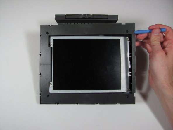
    • Using the plastic opening tool or your fingers, lift up the frame from any edge.

    • Remove the frame from the device.

  7. Cette étape n’est pas traduite. Aidez à la traduire

    : étape 7, image 1 de 3 : étape 7, image 2 de 3 : étape 7, image 3 de 3
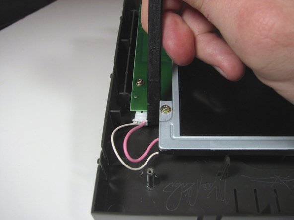
    • Unplug the cable connecting the display to the power supply using the flat end of the spudger to pry the connector away from the circuit board.

    • Alternate applying pressure to the left and right side of the connector to ensure that it does not break.

  8. Cette étape n’est pas traduite. Aidez à la traduire

    : étape 8, image 1 de 1
    • Remove the four 7mm Torx T6 screws.

  9. Cette étape n’est pas traduite. Aidez à la traduire

    : étape 9, image 1 de 2 : étape 9, image 2 de 2
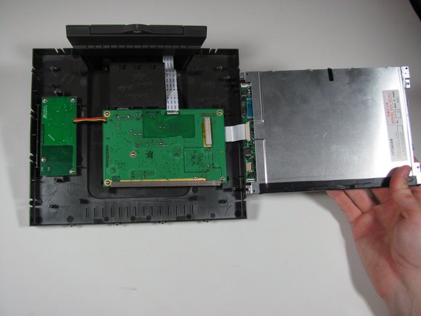
    • Lift up the display from the left edge and flip display over.

    • Do not lift the display too quickly, as the display is still connected to the main circuit board on the right.

  10. Cette étape n’est pas traduite. Aidez à la traduire

    : étape 10, image 1 de 3 : étape 10, image 2 de 3 : étape 10, image 3 de 3
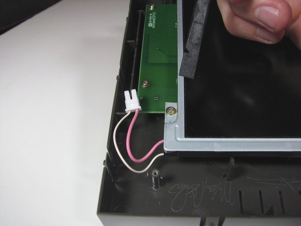
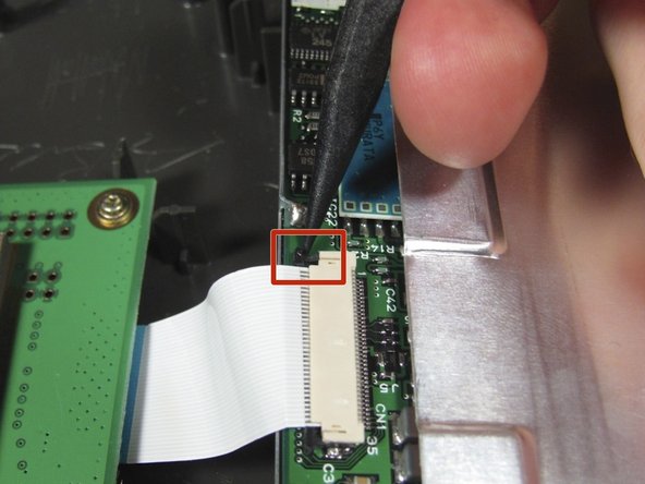
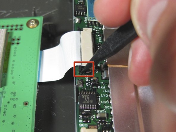
    • Use the spudger to disconnect the ribbon cable from the display by the black pins away from the connector. There is a pin on either side of the connector.

    • Once both pins are released, the ribbon cable should slide easily out.

    • It may be easier if someone else holds the display so the cable does not get ripped out.

  11. Cette étape n’est pas traduite. Aidez à la traduire

    : étape 11, image 1 de 1
    • Remove the display assembly from the device.

  12. Cette étape n’est pas traduite. Aidez à la traduire

    : étape 12, image 1 de 1
    • Remove the five 7mm Torx T6 screws.

  13. Cette étape n’est pas traduite. Aidez à la traduire

    : étape 13, image 1 de 1
    • Desolder the three wires attaching the board to the power supply.

    • In the pictures, the wires are not actually desoldered.

  14. Cette étape n’est pas traduite. Aidez à la traduire

    : étape 14, image 1 de 1
    • Desolder all the ribbon cable attachments from the board.

    • In the pictures, the wires are not actually desoldered.

  15. Cette étape n’est pas traduite. Aidez à la traduire

    : étape 15, image 1 de 1
    • Remove the circuit board from the device.

    • The picture shows the board still attached to the wires, but after desoldering, the board will be completely free from the device.

Ligne d'arrivée

Une autre personne a terminé cette réparation.

Casey Glasgow

Membre depuis le 01/26/14

510 Réputation

5 tutoriels rédigés

Équipe

Cal Poly, Team 9-25, Maness Winter 2014 Membre de l'équipe Cal Poly, Team 9-25, Maness Winter 2014

CPSU-MANESS-W14S9G25

4 membres

5 tutoriels rédigés

0 commentaires

Ajouter un commentaire

Nombre de vues :

Dernières 24 heures : 1

7 derniers jours : 2

30 derniers jours : 2

Total : 117