Aller au contenu principal

Center Chassis Removal (Power Supply Attached)

Conditions préalables uniquement
Ce tutoriel est uniquement destiné à être utilisé comme prérequis d'autres tutoriels. Il ne se suffit pas à lui-même.

Ce dont vous avez besoin

  1. Center Chassis Removal (Power Supply Attached), Uncover the back panel screws: étape 1, image 1 de 2 Center Chassis Removal (Power Supply Attached), Uncover the back panel screws: étape 1, image 2 de 2
    • Before you begin, completely power down and unplug all cables from your console.

    • Use a pair of tweezers to remove the sticker hiding the first screw on the back panel, near the base.

  2. Center Chassis Removal (Power Supply Attached): étape 2, image 1 de 3 Center Chassis Removal (Power Supply Attached): étape 2, image 2 de 3 Center Chassis Removal (Power Supply Attached): étape 2, image 3 de 3
    • For cleaner removal, use an iOpener or hair dryer to heat the sticker.

    • Use a pair of blunt tweezers to peel back the large sticker on the back panel to reveal the second screw.

    • You only need to peel this sticker to where you can access the hidden screw. You don't need to pull it completely off.

    • Technically, these are tamper-evident stickers, but don't worry—Microsoft can't legally void your warranty, as long as you don't damage anything. Have fun!

  3. Center Chassis Removal (Power Supply Attached), Remove the back panel screws: étape 3, image 1 de 1
    Outil utilisé dans cette étape :
    Magnetic Project Mat
    $19.95
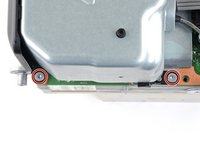
    • Use a T8 Torx driver to remove the two 7.4 mm‑long screws securing the back panel.

    • Throughout this repair, keep track of each screw and make sure it goes back exactly where it came from to avoid damaging your console.

  4. Center Chassis Removal (Power Supply Attached), Unclip the back panel: étape 4, image 1 de 3 Center Chassis Removal (Power Supply Attached), Unclip the back panel: étape 4, image 2 de 3 Center Chassis Removal (Power Supply Attached), Unclip the back panel: étape 4, image 3 de 3
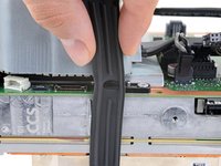
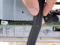
    • Insert the flat end of a spudger into the gap between the back panel and the shell, near the left side of the base.

    • Pry up the back panel to release it from the locking clips.

  5. Center Chassis Removal (Power Supply Attached): étape 5, image 1 de 2 Center Chassis Removal (Power Supply Attached): étape 5, image 2 de 2
    • Insert the flat end of a spudger into the gap between the back panel and the shell, near the right side of the base.

    • Pry up the back panel to release it from the locking clips.

  6. Center Chassis Removal (Power Supply Attached), Remove the back panel: étape 6, image 1 de 3 Center Chassis Removal (Power Supply Attached), Remove the back panel: étape 6, image 2 de 3 Center Chassis Removal (Power Supply Attached), Remove the back panel: étape 6, image 3 de 3
    • Grip the back panel at the opening you just created and pull it up and away from the shell to unclip the long edges.

    • During reassembly, press along the edges of the back panel to snap it into place.

  7. Center Chassis Removal (Power Supply Attached): étape 7, image 1 de 3 Center Chassis Removal (Power Supply Attached): étape 7, image 2 de 3 Center Chassis Removal (Power Supply Attached): étape 7, image 3 de 3
    • The back panel slots into a gap at the top of the shell.

    • Tilt the back panel up and pull it away from the top edge of the shell to release it from the gap.

    • Remove the back panel.

  8. Center Chassis Removal (Power Supply Attached), Remove the fan screws: étape 8, image 1 de 1
    • Use a T8 Torx driver to remove the three screws securing the fan to the center chassis:

    • One 10.5 mm pancake screw

    • Two 8.8 mm screws

  9. Center Chassis Removal (Power Supply Attached), Disconnect the fan cable: étape 9, image 1 de 3 Center Chassis Removal (Power Supply Attached), Disconnect the fan cable: étape 9, image 2 de 3 Center Chassis Removal (Power Supply Attached), Disconnect the fan cable: étape 9, image 3 de 3
    Outil utilisé dans cette étape :
    Tweezers
    $4.99
    • Use your fingers or a pair of blunt tweezers to grip the edges of the fan cable connector, and pull up to disconnect it from the center chassis.

    • Always pull cables by their connectors and not the wires themselves.

    • During reassembly, route the fan cable underneath its small cable guide on the fan housing so it doesn't interfere with the back panel.

  10. Center Chassis Removal (Power Supply Attached), Remove the fan: étape 10, image 1 de 2 Center Chassis Removal (Power Supply Attached), Remove the fan: étape 10, image 2 de 2
    • Slide the fan out of its slot to remove it.

    • During reinstallation, note that the fan can only be installed one way—make sure Master Chief is facing you.

    • If you're replacing the fan, a new fan might not include the plastic installation bracket, which is attached to the fan with four T10 Torx screws. This isn't pictured in this guide.

  11. Center Chassis Removal (Power Supply Attached), Unlatch the base: étape 11, image 1 de 3 Center Chassis Removal (Power Supply Attached), Unlatch the base: étape 11, image 2 de 3 Center Chassis Removal (Power Supply Attached), Unlatch the base: étape 11, image 3 de 3
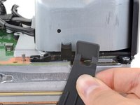
    • Use the flat end of a spudger to lift up on the locking tab holding the base to the shell.

  12. Center Chassis Removal (Power Supply Attached), Twist and remove the base: étape 12, image 1 de 3 Center Chassis Removal (Power Supply Attached), Twist and remove the base: étape 12, image 2 de 3 Center Chassis Removal (Power Supply Attached), Twist and remove the base: étape 12, image 3 de 3
    • Grip the base and rotate it counterclockwise to unlock it from the shell.

    • You may need to hold the locking tab open while you get the base started.

    • Remove the base.

    • During reassembly, drop the base tabs into their holes on the shell and twist clockwise until the base snaps into the interior locking tab.

    • When locked in place, the "Hello from Seattle" line will be parallel with the device's sides.

  13. Center Chassis Removal (Power Supply Attached), Remove the optical drive screws: étape 13, image 1 de 2 Center Chassis Removal (Power Supply Attached), Remove the optical drive screws: étape 13, image 2 de 2
    • Use a T8 Torx driver to remove the two 8.8 mm screws securing the optical drive's vibration isolator to the shell: one on the base and one on the top of the isolator.

  14. Center Chassis Removal (Power Supply Attached), Remove the vibration isolator: étape 14, image 1 de 3 Center Chassis Removal (Power Supply Attached), Remove the vibration isolator: étape 14, image 2 de 3 Center Chassis Removal (Power Supply Attached), Remove the vibration isolator: étape 14, image 3 de 3
    • Lift up the optical drive's vibration isolator to remove it.

    • The vibration isolator grips the sides of the optical drive with silicone pads, so you may need to "walk" the isolator off of the drive to slip it off each side.

    • During reassembly, ensure the vibration isolator is pushed down and around both edges of the optical drive, so it sits flush with the rest of the center chassis.

  15. Center Chassis Removal (Power Supply Attached), Disconnect the power and data cables: étape 15, image 1 de 3 Center Chassis Removal (Power Supply Attached), Disconnect the power and data cables: étape 15, image 2 de 3 Center Chassis Removal (Power Supply Attached), Disconnect the power and data cables: étape 15, image 3 de 3
    Outil utilisé dans cette étape :
    Tweezers
    $4.99
    • Use a pair of blunt tweezers to grip the edges of the optical drive power connector and pull up to disconnect it from the optical drive.

    • Always pull cables by their connectors and not the wires themselves.

    • Use your fingers to pull up and disconnect the data cable from the optical drive.

  16. Center Chassis Removal (Power Supply Attached), Remove the optical drive: étape 16, image 1 de 2 Center Chassis Removal (Power Supply Attached), Remove the optical drive: étape 16, image 2 de 2
    • Grip the top edge of the optical drive and pull it out of its slot in the shell to remove it.

    • During reassembly, align the pegs on the bottom edge of the optical drive with the guide holes on the bottom of the shell.

    • If the drive is misaligned, the top vibration isolator will not be able to be installed correctly, and the disc reader will be misaligned with the front of the console.

  17. Center Chassis Removal (Power Supply Attached), Disconnect the USB port cable: étape 17, image 1 de 3 Center Chassis Removal (Power Supply Attached), Disconnect the USB port cable: étape 17, image 2 de 3 Center Chassis Removal (Power Supply Attached), Disconnect the USB port cable: étape 17, image 3 de 3
    • The ribbon cables and their connectors are extremely fragile, so always open locking tabs gently and pull cables slowly.

    • Use the flat end of a spudger to flip open the metal locking tab on the USB port ribbon cable.

    • During reassembly, gently snap the metal locking tab back into place once the cable has been inserted.

  18. Center Chassis Removal (Power Supply Attached): étape 18, image 1 de 2 Center Chassis Removal (Power Supply Attached): étape 18, image 2 de 2
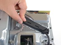
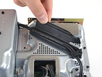
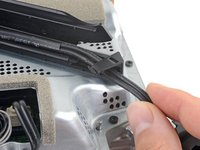
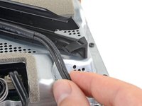
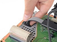
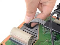
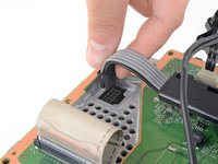
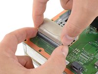
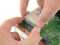
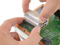
    • Use a pair of tweezers to pull up on the black plastic pull tab to disconnect the USB port cable.

    • Pull only on the pull tab, not the cable itself.

    • If the USB port cable feels adhered to the metal chassis, use an apply an iOpener or hair dryer to heat the cable. Depending on your model of Xbox, you may also need to slide an opening pick under the cable to separate the adhesive.

  19. Center Chassis Removal (Power Supply Attached), Disconnect the power button cable: étape 19, image 1 de 3 Center Chassis Removal (Power Supply Attached), Disconnect the power button cable: étape 19, image 2 de 3 Center Chassis Removal (Power Supply Attached), Disconnect the power button cable: étape 19, image 3 de 3
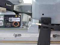
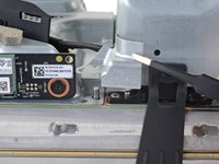
    • Use the pointed end of a spudger to depress the metal tab on the side of the power button cable's board connector.

    • With the metal tab depressed, use a pair of tweezers to pull up on the pull tab to disconnect the power button cable from the center chassis.

    • Pull only on the pull tab, not the cable itself.

    • Don't pull on the cable without depressing the metal tab, otherwise you risk damaging either the cable or the connector.

    • During reassembly, the cable should lightly "snap" into place when inserted.

  20. Center Chassis Removal (Power Supply Attached), Remove the chassis screws: étape 20, image 1 de 1
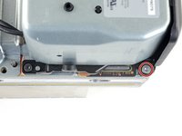
    • Use a T8 Torx driver to remove the three 7.4 mm screws securing the center chassis assembly to the shell.

  21. Center Chassis Removal (Power Supply Attached), Peel up the USB port cable: étape 21, image 1 de 2 Center Chassis Removal (Power Supply Attached), Peel up the USB port cable: étape 21, image 2 de 2
    • Gently peel the taped USB port ribbon cable off of the heatsink.

    • Depending on your model of Xbox, the adhesive may be on the underside of the cable. If so, use an iOpener or hair dryer to heat the cable.

  22. Center Chassis Removal (Power Supply Attached), Remove the center chassis assembly: étape 22, image 1 de 3 Center Chassis Removal (Power Supply Attached), Remove the center chassis assembly: étape 22, image 2 de 3 Center Chassis Removal (Power Supply Attached), Remove the center chassis assembly: étape 22, image 3 de 3
    • The center chassis is aligned to the shell with guide pegs. These pegs will need to slide out of their slots to allow the chassis to be lifted out.

    • Grip the center chassis and pull it towards the green fan grille at the top of the shell, uncoupling the guide pegs from the shell.

    • Lift out the center chassis assembly to remove it from the shell.

    • During reassembly, make sure neither of the ribbon cables get pinched as you lower the center chassis into the shell.

  23. Center Chassis Removal (Power Supply Attached), Unlatch the chassis strap: étape 23, image 1 de 3 Center Chassis Removal (Power Supply Attached), Unlatch the chassis strap: étape 23, image 2 de 3 Center Chassis Removal (Power Supply Attached), Unlatch the chassis strap: étape 23, image 3 de 3
    • Unlatch the chassis strap from the right side of the power supply.

  24. Center Chassis Removal (Power Supply Attached): étape 24, image 1 de 3 Center Chassis Removal (Power Supply Attached): étape 24, image 2 de 3 Center Chassis Removal (Power Supply Attached): étape 24, image 3 de 3
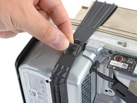
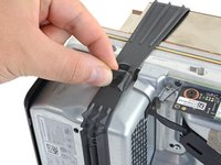
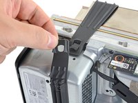
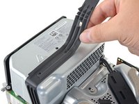
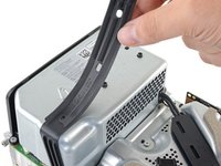
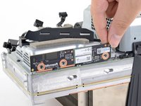
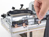
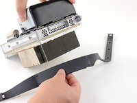
    • Pull the chassis strap over and off of the power supply.

    • Once the strap is off of the power supply, set the loose section to the side.

  25. Center Chassis Removal (Power Supply Attached), Remove the power cable port: étape 25, image 1 de 1
    • Use a T8 Torx driver to remove the three screws securing the power cable port to the chassis:

    • Two 13.1 mm screws

    • One 35 mm screw

  26. Center Chassis Removal (Power Supply Attached): étape 26, image 1 de 2 Center Chassis Removal (Power Supply Attached): étape 26, image 2 de 2
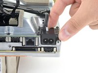
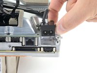
    • Lift the power connector out of its recess in the chassis.

  27. Center Chassis Removal (Power Supply Attached), De-route the power cables: étape 27, image 1 de 2 Center Chassis Removal (Power Supply Attached), De-route the power cables: étape 27, image 2 de 2
    • Unlatch and open the lid on the power cable's plastic guide.

  28. Center Chassis Removal (Power Supply Attached): étape 28, image 1 de 2 Center Chassis Removal (Power Supply Attached): étape 28, image 2 de 2
    • Lift the power cable out from underneath the extra section of the cable guide.

  29. Center Chassis Removal (Power Supply Attached), Remove the corner cover: étape 29, image 1 de 1
    • Use a T8 Torx driver to remove the 8.8 mm screw securing the power supply corner cover.

  30. Center Chassis Removal (Power Supply Attached): étape 30, image 1 de 2 Center Chassis Removal (Power Supply Attached): étape 30, image 2 de 2
    Outil utilisé dans cette étape :
    Tweezers
    $4.99
    • Your Xbox may not have this cover depending on the model.

    • Use your fingers or a pair of tweezers to lift and remove the power supply corner cover.

  31. Center Chassis Removal (Power Supply Attached), Remove the accessory antenna board: étape 31, image 1 de 1
    • Use a T8 Torx driver to remove the three 9.6 mm screws securing the accessory antenna board to the center chassis.

  32. Center Chassis Removal (Power Supply Attached): étape 32, image 1 de 3 Center Chassis Removal (Power Supply Attached): étape 32, image 2 de 3 Center Chassis Removal (Power Supply Attached): étape 32, image 3 de 3
    • Grip the antenna board and pull it directly away from the center chassis to disconnect it.

    • During reassembly, align the board's connector with the port on the center chassis and press to reconnect.

  33. Center Chassis Removal (Power Supply Attached), Remove the board shield: étape 33, image 1 de 1
    • Use a T8 Torx driver to remove the nine screws securing the board shield:

    • Six 8.8 mm black screws

    • Two 35 mm silver screws

    • One 13.1 mm silver screw

  34. Center Chassis Removal (Power Supply Attached): étape 34, image 1 de 3 Center Chassis Removal (Power Supply Attached): étape 34, image 2 de 3 Center Chassis Removal (Power Supply Attached): étape 34, image 3 de 3
    • Lift up the board shield to remove it from the center chassis.

  35. Center Chassis Removal (Power Supply Attached), Remove the chassis strap: étape 35, image 1 de 3 Center Chassis Removal (Power Supply Attached), Remove the chassis strap: étape 35, image 2 de 3 Center Chassis Removal (Power Supply Attached), Remove the chassis strap: étape 35, image 3 de 3
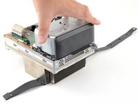
    • Disconnect the chassis strap from the locking tabs on either side of the power supply.

  36. Center Chassis Removal (Power Supply Attached): étape 36, image 1 de 2 Center Chassis Removal (Power Supply Attached): étape 36, image 2 de 2
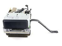
    • Remove the chassis strap.

  37. Center Chassis Removal (Power Supply Attached), Disconnect the motherboard: étape 37, image 1 de 3 Center Chassis Removal (Power Supply Attached), Disconnect the motherboard: étape 37, image 2 de 3 Center Chassis Removal (Power Supply Attached), Disconnect the motherboard: étape 37, image 3 de 3
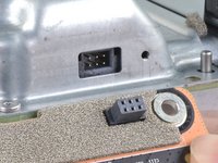
    • Grip and compress the locking tab on the 10-pin power connector.

    • While compressing the locking tab, lift the connector straight up to disconnect it from the board.

    • Always pull cables by their connectors and not the wires themselves.

  38. Center Chassis Removal (Power Supply Attached): étape 38, image 1 de 3 Center Chassis Removal (Power Supply Attached): étape 38, image 2 de 3 Center Chassis Removal (Power Supply Attached): étape 38, image 3 de 3
    • Grip the base of the interconnect cable connector with your fingers.

    • Depress each side of the connector to unlock the cable locking tabs.

    • With the locking tabs depressed, grip the edges of the interconnect cable and pull it straight out of the connector to disconnect it.

    • With the locking tabs depressed correctly, the interconnect cable will slide out with very little force.

    • During reassembly, the interconnect cable should "snap" into place when fully inserted.

  39. Center Chassis Removal (Power Supply Attached), Remove the silver power supply screws: étape 39, image 1 de 2 Center Chassis Removal (Power Supply Attached), Remove the silver power supply screws: étape 39, image 2 de 2
    • Use a T8 Torx driver to remove the three 35 mm‑long silver screws from the power supply—leave the fourth black screw in place.

  40. Center Chassis Removal (Power Supply Attached), Remove the center chassis: étape 40, image 1 de 3 Center Chassis Removal (Power Supply Attached), Remove the center chassis: étape 40, image 2 de 3 Center Chassis Removal (Power Supply Attached), Remove the center chassis: étape 40, image 3 de 3
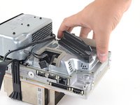
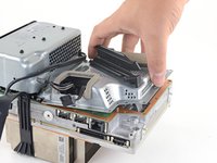
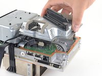
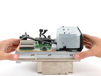
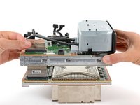
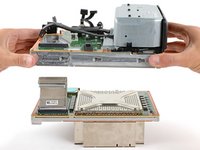
    • Grip the edges of the center chassis (not the power supply) and lift it off of the motherboard and heatsink assembly, routing the interconnect cable through its cutout.

Ligne d'arrivée

Carsten Frauenheim

Membre depuis le 03/10/20

135 594 Réputation

371 tutoriels rédigés

Équipe

iFixit Membre de l'équipe iFixit

Staff

118 membres

19 430 tutoriels rédigés

0 commentaires

Ajouter un commentaire

Nombre de vues :

Dernières 24 heures : 1

7 derniers jours : 4

30 derniers jours : 4

Total : 10