Cette version peut contenir des modifications incorrectes. Passez au dernier aperçu vérifié.
Ce dont vous avez besoin
-
Cette étape n’est pas traduite. Aidez à la traduire
-
Loosen the screws using Phillips #01 screwdriver with the extension attached.
-
-
Cette étape n’est pas traduite. Aidez à la traduire
-
After removing the two screws securing the Hard Drive to the bottom case, remove the panel to reveal the hard drive.
-
-
Cette étape n’est pas traduite. Aidez à la traduire
-
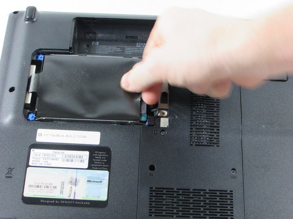
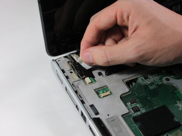
Locate the tab of the black Mylar film on the right hand side of the hard drive.
-
Gently grip it with your thumb and index finger.
-
-
Cette étape n’est pas traduite. Aidez à la traduire
-
Pull the Hard Drive to the right to loosen the it from the frame.
-
The left side of the hard drive will pop up and should slide out freely until you see the black connector on it's right side, connecting it to the computer.
-
-
Cette étape n’est pas traduite. Aidez à la traduire
-
Turn the Hard Drive over and grasp the Hard Drive with one hand as you grip the connector with the other hand to remove the connector from the hard drive.
-
-
Cette étape n’est pas traduite. Aidez à la traduire
-
Remove the six screws. Four are marked with a keyboard icons, two are located on the top corner.
-
Remove the three screws located in the battery port.
-
-
Cette étape n’est pas traduite. Aidez à la traduire
-
Use a plastic spudger to gently un-clip the top panel above keyboard.
-
-
Cette étape n’est pas traduite. Aidez à la traduire
-
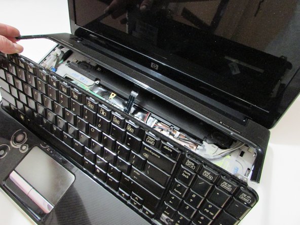
Once the top panel is propped open, remove the three 4mm silver screws located at the top of the keyboard with a Philips head screw driver, size #1.
-
Flip keyboard forward and raise the keyboard off the frame.
-
-
Cette étape n’est pas traduite. Aidez à la traduire
-
Once you have removed the three screws, gently lift the keyboard away from the laptop.
-
-
-
Cette étape n’est pas traduite. Aidez à la traduire
-
Use plastic spudger to flip up the black strip on the ZIF connector that connects the ribbon cable to the motherboard.
-
-
Cette étape n’est pas traduite. Aidez à la traduire
-
Remove the film from system board to then safely remove the keyboard.
-
-
Cette étape n’est pas traduite. Aidez à la traduire
-
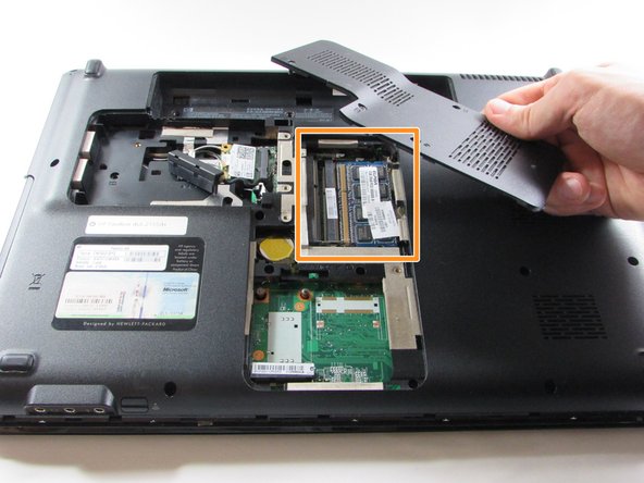
Flip the laptop over and locate the memory module panel and loosen the 3 screws holding down the panel.
-
Remove the panel to expose the 2 memory modules.
-
-
Cette étape n’est pas traduite. Aidez à la traduire
-
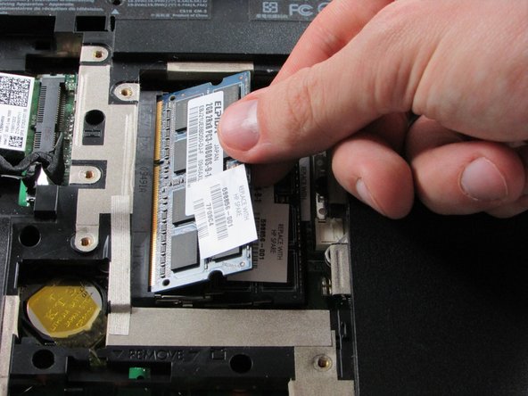
Remove the memory modules by using your index finger and thumb to spread apart the silver retaining tabs on both sides of the modules. After spreading the tabs apart, lift and pull the module out at an angle.
-
Repeat this action for the second memory module that is directly under the first.
-
-
Cette étape n’est pas traduite. Aidez à la traduire
-
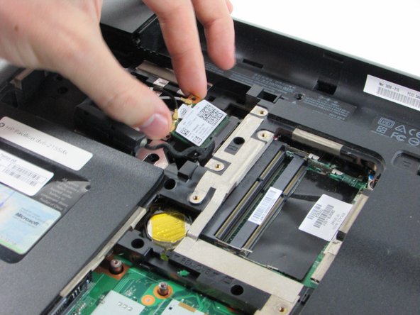
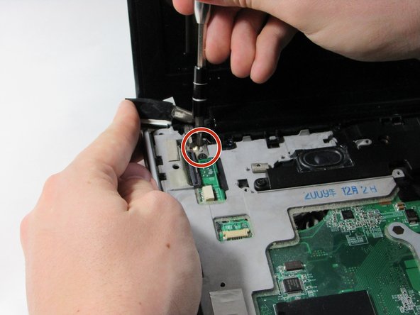
Locate the WLAN module located in the hard drive panel and remove the single silver screw holding the WLAN module.
-
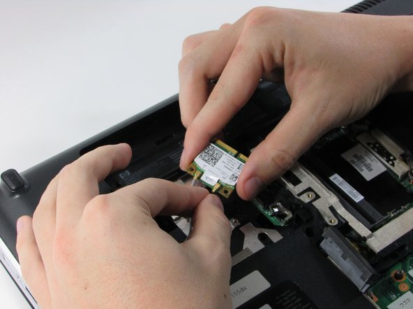
After screw is removed, gently disconnect the WLAN module using your thumb and index finger from the connector.
-
Disconnect the two WLAN antenna cables (white and black) attached to the WLAN module by gently lifting and holding onto the gold base.
-
-
Cette étape n’est pas traduite. Aidez à la traduire
-
Remove the remaining seven screws screws on the bottom of the laptop.
-
The screws are 7mm long and the head is 4mm wide.
-
-
Cette étape n’est pas traduite. Aidez à la traduire
-
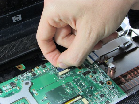
Disconnect the LED board and power button cables from the connector on the system board by pulling the blue Mylar tabs toward the display screen.
-
-
Cette étape n’est pas traduite. Aidez à la traduire
-
Disconnect the display cable by lifting the Mylar tab up towards the screen.
-
-
Cette étape n’est pas traduite. Aidez à la traduire
-
Remove the yellow or clear tape in the upper right hand corner to reveal the webcam/microphone cables.
-
Using a plastic flat spudger, disconnect the silver webcam/microphone cable from the system board by pulling the white connector out with the spudger.
-
-
Cette étape n’est pas traduite. Aidez à la traduire
-
Disconnect the power connector cable by using the point of the plastic spudger. continue to slide the plastic part until it is completely removed or you are able to grab the plastic with your fingers.
-
-
Cette étape n’est pas traduite. Aidez à la traduire
-
Now disconnect the audio cable (red and white) also using the flat plastic spudger. Gently pry the black piece of the connector away from the white connecting dock it sits in.
-
-
Cette étape n’est pas traduite. Aidez à la traduire
-
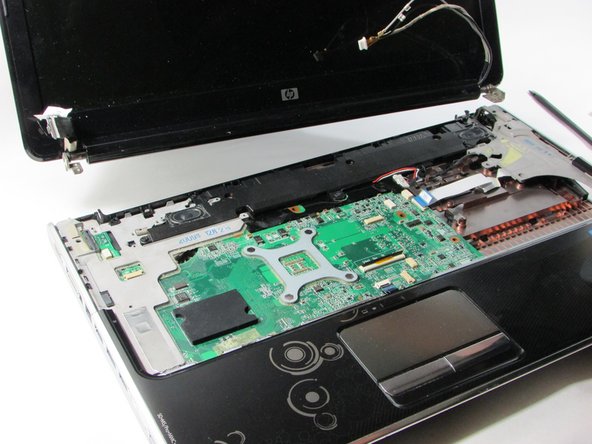
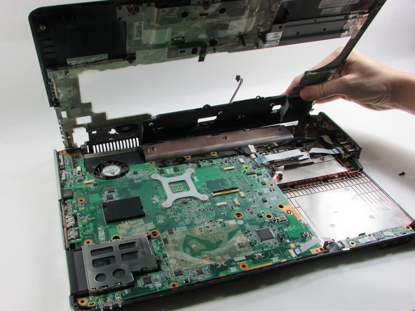
Remove the four screws that connect the display to the laptop, two screws per side.
-
Now you can safely remove the screen from the body of the laptop.
-
-
Cette étape n’est pas traduite. Aidez à la traduire
-
After removal of the display, you will see and need to remove four black screws
-
-
Cette étape n’est pas traduite. Aidez à la traduire
-
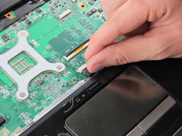
Disconnect the touch pad ribbon cable from the system board by gripping and pulling the blue tab toward you.
-
-
Cette étape n’est pas traduite. Aidez à la traduire
-
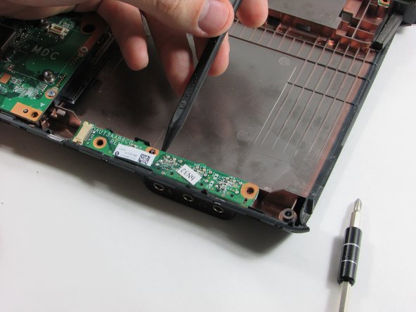
Starting in the front of the laptop, use a flat plastic spudger to gently pry the silver/chrome plastic bar off of the front of the laptop.
-
Once the silver/chrome bar is removed, the laptop cover should be loosened enough to remove.
-
-
Cette étape n’est pas traduite. Aidez à la traduire
-
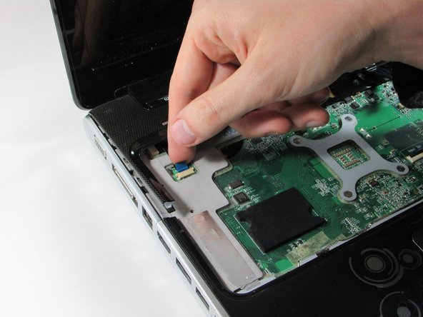
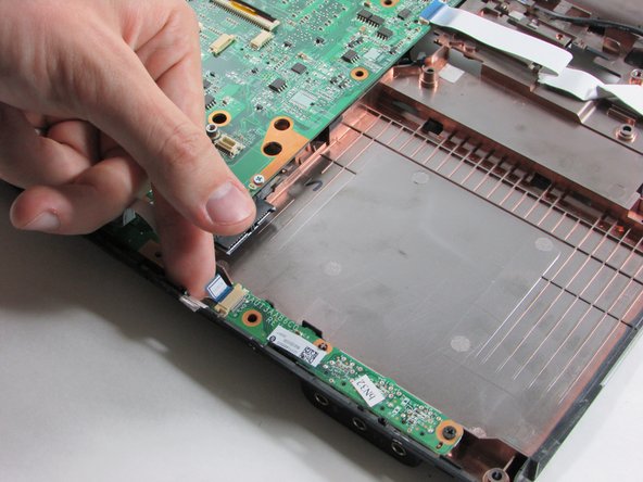
Locate and disconnect the audio/infrared cable from the system board on the right hand side by pulling the blue and white tab to the left.
-
-
Cette étape n’est pas traduite. Aidez à la traduire
-
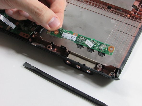
Remove the 2 black screws on the bottom right hand corner of the system board.
-
The headphone/microphone jack will now be lose and you can remove it from the system board.
-


Équipe

UMass Dartmouth, Team 2-2, Isaacson Fall 2016 Membre de l'équipe UMass Dartmouth, Team 2-2, Isaacson Fall 2016
UMASSD-ISAACSON-F16S2G2
3 membres
5 tutoriels rédigés