Aller au contenu principal

Cette version peut contenir des modifications incorrectes. Passez au dernier aperçu vérifié.

Ce dont vous avez besoin

  1. , Boîtier inférieur: étape 1, image 1 de 1
    Outil utilisé dans cette étape :
    P5 Pentalobe Screwdriver Retina MacBook Pro and Air
    $5.99
    J'achète
    • Éteignez et fermez votre ordinateur. Posez-le sur une surface douce, la partie supérieure vers le bas.

    • Retirez les dix vis suivantes :

    • Deux vis pentalobes 8 mm 5-points

    • Huit vis pentalobes 2.5 mm 5-points

    • Le tournevis spécial nécessaire pour enlever les 5 points vis pentalobes peut être trouvé ici.

  2. : étape 2, image 1 de 1
    • Calez vos doigts entre l'écran et le boîtier inférieur et tirez vers le haut pour faire apparaître le boîtier inférieur de l'ordinateur.

  3. , Connecteur de la batterie: étape 3, image 1 de 2 , Connecteur de la batterie: étape 3, image 2 de 2
    • Au cours de cette étape, vous allez débrancher la batterie pour éviter de court-circuiter des composants pendant la réparation.

    • Utilisez l'extrémité plate d'une spatule (spudger) pour faire levier sur les deux côtés courts du connecteur de la batterie afin de le déconnecter de sa prise sur la carte mère.

    • Repliez légèrement la nappe de la batterie pour l'éloigner de la carte mère pour éviter que le connecteur ne se rabatte accidentellement et n'entre en contact avec sa prise.

  4. Cette étape n’est pas traduite. Aidez à la traduire

    : étape 4, image 1 de 2 : étape 4, image 2 de 2
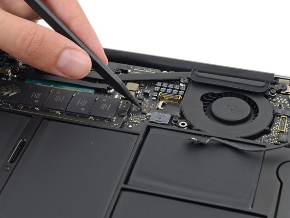
    • Use the tip of a spudger to carefully push on each side of the iSight camera cable connector to loosen it out of its socket on the logic board.

    • We recommend you gently "walk" the connector out of its socket.

  5. Cette étape n’est pas traduite. Aidez à la traduire

    : étape 5, image 1 de 2 : étape 5, image 2 de 2
    • Peel the iSight camera cable up off the adhesive securing it to the fan.

  6. Cette étape n’est pas traduite. Aidez à la traduire

    : étape 6, image 1 de 2 : étape 6, image 2 de 2
    • Use the tip of a spudger to carefully flip up the retaining flap on the fan cable ZIF socket.

    • Be sure you are prying up on the hinged retaining flap, not the socket itself.

  7. Cette étape n’est pas traduite. Aidez à la traduire

    : étape 7, image 1 de 1
    • Remove the following three screws securing the fan to the upper case:

    • Two 5.5 mm T5 Torx screws

    • One 4.6 mm T5 Torx screw

    • In some models this is a 3.6 mm T5 Torx screw.

  8. Cette étape n’est pas traduite. Aidez à la traduire

    : étape 8, image 1 de 3 : étape 8, image 2 de 3 : étape 8, image 3 de 3
    • Lift, but do not remove the fan out of its recess in the upper case.

    • Carefully pull the fan ribbon cable out of its socket as you remove the fan from the Air.

  9. Cette étape n’est pas traduite. Aidez à la traduire

    : étape 9, image 1 de 1
    • Remove the four 2.5 mm T5 Torx screws securing the heat sink to the logic board.

  10. Cette étape n’est pas traduite. Aidez à la traduire

    : étape 10, image 1 de 2 : étape 10, image 2 de 2
    • If the heat sink seems to be stuck to the logic board after removing all four screws, use a spudger to carefully separate the heat sink from the face of the CPU.

    • Remove the heat sink from the logic board.

    • When reinstalling the heat sink, be sure to apply a new layer of thermal paste. If you have never applied thermal paste before, we have a guide that makes it easy.

Ligne d'arrivée

3 autres ont terminé cette réparation.

Sam Goldheart

Membre depuis le 10/18/12

465 851 Réputation

538 tutoriels rédigés

Équipe

iFixit Membre de l'équipe iFixit

Staff

135 membres

17 194 tutoriels rédigés

3 commentaires

you should seriously note the danger of the cpu screw holders. apple for some reason decided to attach the fricken screw receivers/standoffs via surface mount. they dont have a bottom cap either. use a screw slightly too long or turn too far and pop(screw pushes against motherboard and pops the holder off)... one corner is unable to be screwed in. ask me how i learned this...lol...I cant see how this design decision helps anything but apples wallet. the other side of the board has components smds as well so its not like a really short through hole was undo-able.

John W - Réponse

There is step missing between 3 and 4. There is another ribbon cable over fan that is still there in step 3 but gone in step 4.

Bogdaniec Ze Zbyszka - Réponse

The step 3 and 4, there should be a step removing the I/O cable. I/O cable must be removed or disassembled to access iSight camera cable. The I/O cable is covering the entire iSight cable, and without removing, accessing the iSight cable will extremely difficult.

ChiKen - Réponse

Ajouter un commentaire

Nombre de vues :

Dernières 24 heures : 0

7 derniers jours : 19

30 derniers jours : 50

Total : 4,828