Introduction
This guide is used for the replacement of the Motherboard on your Nintendo Switch Pro Controller. Take precaution when completing this guide because it involves the removal of a lithium-ion battery. If the battery is swollen, check out this resource on how to dispose of a swollen battery. To Complete this guide correctly you must complete steps eight and nine with caution so as to not damage the white ribbon. In addition, you must be able to solder. If you do not know how to solder, check out this resource on how to solder. Be careful when removing the plastic pieces and the internal circuit board of the controller so as to not damage the components.
Ce dont vous avez besoin
-
-
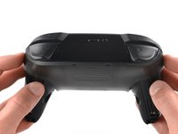
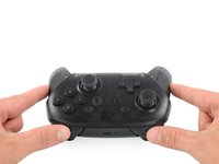
Flip the controller over so the model stickers face the ceiling.
-
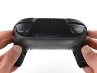
Use a JIS #00 screwdriver to remove the two black 8.4 mm screws that secure the handles, located at the ends of the handles.
-
-
-
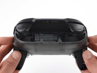
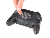
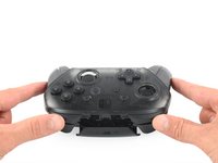
Carefully remove the handle covers by pulling them away from the main body.
-
-
-
Use a JIS #00 screwdriver to remove the four silver 6.8 mm screws that secure the clear back plastic cover.
-
-
-
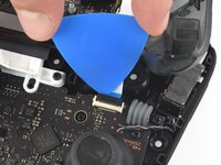
Carefully pry away the clear plastic cover using your fingernail.
-
-
-
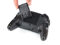
Remove the lithium-ion battery by using a fingernail or plastic opening tool to pry it up on the left side.
-
-
-
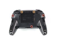
Use a Phillips #1 screwdriver to remove the five 5 mm screws from the back of the controller.
-
The two case screws above the handgrips and the single case screw below the battery bay have a shallow seat. These three screws can be easily removed.
-
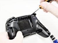
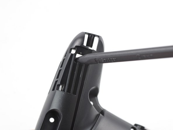
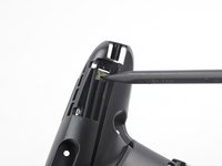
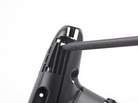
The two case screws adjacent to the ZR and ZL shoulder buttons have a deep seat. Use an extension or a Phillips screwdriver with a longer shaft to reach these screws.
the 2 screws up at the top are unreachable with the standard fixit kit just a heads up
Seconded. the screws are located too deep below the plastic slot, and the bit holding bulge is too wide for the small aperture (similarly with the flexible extension). the bit length is too shallow to reach.
An alternative driver with a much narrower & longer shaft is required, which will likely not come with interchangeable bits.
I would say it is possible to reach the top left screw, just not the top right - there is a gap in the top left that allows you to slightly bend the standard driver outward to turn it while still making adequate contact.
An update: I was actually able to remove the top right one in a really hacky way - inserting the Phillips #0 bit into the #4 hex bit, and then using that in the standard driver. This added just enough length to successfully reach and make full contact with the screw!
Using the #4 hex bit as an extension was the exact "hack" I needed to get rid of the drift finally. Thank you. You're a lifesaver.
Das #4 Hex Bit als Verlängerung für das Kreuzschlitz Bit zu nutzen ist zwar etwas eng, aber es erspart einem wirklich einen zusätzlichen Schraubendreher.
-
-
-
-
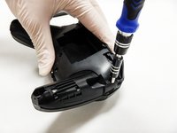
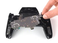
Delicately take off the plastic cover from the controller.
Didn't realize there is adhesive holding the front cover onto the unit. It's located inside of the handles. Just a bit of force there helped, just be careful of the cable.
-
-
-
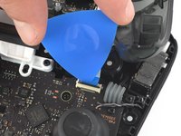
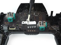
Use the tip of an opening pick to open the black flap of the ZIF connector by pushing it upwards.
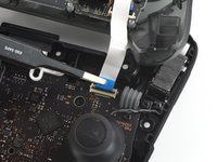
Having just completed this repair, I noted that this ribbon cable can disconnect on either side. It is easier to disconnect and reconnect from the other side than what is shown in my experience.
@acestronautical is right! much easier to remove the ribbon cable from the button board, connect to the base board and then connect back to the button board. Thank you @acestronautical
-
-
Outil utilisé dans cette étape :Tweezers$4.99
-
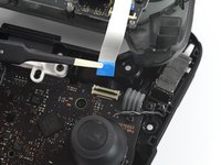
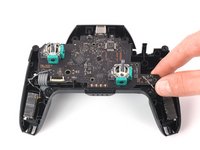
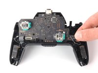
Use your fingers or a pair of blunt nose tweezers to disconnect the interconnect cable from its connector.
You don't need to disconnect this as long as you are fine with keeping it close by so as not to rip the ribbon cable.
-
-
-
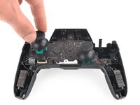
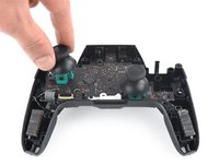
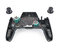
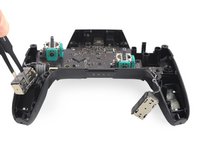
With light force pull the two joystick caps off of the controller.
-
-
-
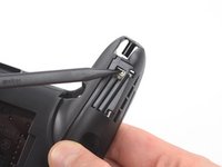
Insert the tip of a spudger from the back into the hole on the right controller handle.
-
Push the spudger through the hole to loosen the adhesive which is holding rumble modules in their places.
-
-
-
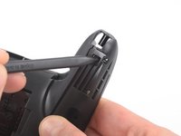
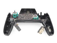
Insert the tip of a spudger from the back into the hole on the left controller handle.
-
Push the spudger through the hole to loosen the adhesive which is holding rumble modules in their places.
-
-
Outil utilisé dans cette étape :Tweezers$4.99
-
Use a pair tweezers to lift the modules out of their places.
-
-
-
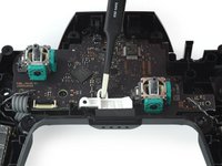
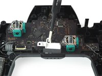
Use a Phillips screwdriver to remove the four 5 mm-long screws securing the motherboard.
-
-
-
Use your thumb or a pair of tweezers to to take off the white LED light housing.
-
-
-
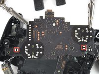
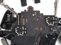
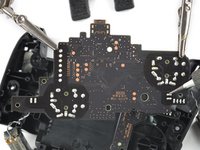
Lift the motherboard carefully as to not damage the wires and flip it to reveal the backside.
-
-
-
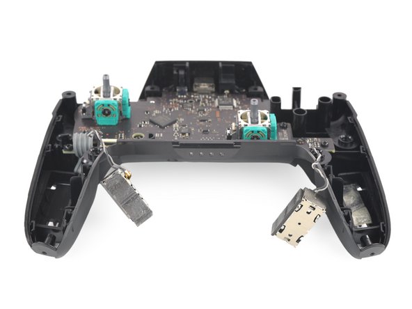
Desolder the rumble motor solder points on either side of the motherboard.
-
Remove the rumble modules.
-
-
-
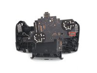
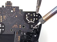
Remove the main power cable from the highlighted pins by de-soldering them.
-
Remove the motherboard.
-


To reassemble your device, follow these instructions in reverse order.
To reassemble your device, follow these instructions in reverse order.
Annulation : je n'ai pas terminé ce tutoriel.
4 autres ont terminé cette réparation.

Équipe

The Citadel Military College of South Carolina, Team S2-G9, Eggleston Fall 2020 Membre de l'équipe The Citadel Military College of South Carolina, Team S2-G9, Eggleston Fall 2020
CMCSC-EGGLESTON-F20S2G9
3 membres
18 tutoriels rédigés
Be carefull, these screws are super easy to strip even with the right tools.
Lukas Eberharter - Réponse
I tried editing these instructions after I had trouble with stripping screws, but it doesn't seem to take. The issue is that these are JIS and not Phillips screws. They are VERY similar looking but a Phillips head screwdriver will strip the screws.
Isaac Webb - Réponse
I tried using a Philips #00 screwdriver but it didn’t work
vincent ingrassia - Réponse
Don't even think about trying Phillips. There are some other guides online that say you'll be fine, but they're wrong. Even one attempt with Phillips WILL strip these, and you will never, ever get this controller open once that happens. Even with JIS they're really hard to get out and really easy to strip.
Luke T. Allen - Réponse