Cette version peut contenir des modifications incorrectes. Passez au dernier aperçu vérifié.
Ce dont vous avez besoin
-
-
Utilisez une pièce pour faire tourner la vis qui verrouille la batterie, de 90 degrés dans le sens des aiguilles d'une montre.
-
-
Cette étape n’est pas traduite. Aidez à la traduire
-
Pull the keyboard release tabs toward you and lift up on the keyboard until it pops free.
-
Flip the keyboard over, away from the screen, and rest it face-down on the trackpad area.
-
-
Cette étape n’est pas traduite. Aidez à la traduire
-
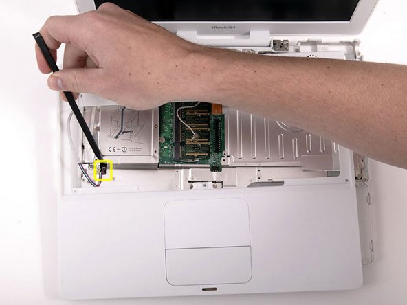
Push the wire clasp away from the AirPort card and toward the display, then rotate up to free it from the RAM shield.
-
-
Cette étape n’est pas traduite. Aidez à la traduire
-
Remove the four silver Phillips screws that secure the RAM shield.
-
-
Cette étape n’est pas traduite. Aidez à la traduire
-
Grasp the metal bracket on top of the RAM shield and pull upward to remove the shield.
-
-
-
Utilisez une punaise (ou un autre outil très fin) pour retirer les patins en caoutchouc du boîtier inférieur.
-
-
-
Passez une spatule le long de la jointure entre le boîtier supérieur et le boîtier inférieur à l'avant de l'ordinateur pour détacher les attaches du boîtier inférieur. Tirez le boîtier inférieur vers le haut et déplacez la spatule autant que nécessaire jusqu'à entendre trois clics distincts.
-
-
-
Il y a trois attaches au niveau du lecteur optique que vous devez détacher avant que le boîtier inférieur sorte. Passez une spatule le long du boîtier inférieur, au-dessus de la fente du lecteur optique et déplacez-la vers l'arrière du boitier jusqu'à entendre trois clics distincts.
-
-
Cette étape n’est pas traduite. Aidez à la traduire
-
Remove the 4 Phillips screws from the bottom shield.
-
-
-
-
Retirez les deux vis cruciformes fixant la carte de raccordement.
-
-
Cette étape n’est pas traduite. Aidez à la traduire
-
Deroute the cable from around the optical drive, removing tape as necessary, and angle the DC-In board out of its compartment.
-
-
-
Retirez les deux vis cruciformes du compartiment de la batterie.
-
-
Cette étape n’est pas traduite. Aidez à la traduire
-
Turn over the computer and open it.
-
Pry up the magnet covering a Phillips screw near the middle of the computer.
-
-
-
Retirez les 7 vis suivantes sur les bords de la zone du clavier :
-
Trois cruciformes de 2 mm le long du bord droit
-
Une cruciforme de 4,5 mm sous l'aimant
-
Une cruciforme de 6 mm avec une petite tête dans le coin inférieur gauche
-
Deux cruciformes de 6 mm avec de grandes têtes, une dans le coin supérieur gauche et une au milieu
-
-
-
Soulevez le boîtier supérieur par le côté droit et utilisez une spatule (spudger) ou votre doigt pour déconnecter le connecteur du trackpad caché sous la languette en plastique blanc. En raison des variations de modèle, le connecteur de votre trackpad peut être différent de celui ci-contre.
-
-
-
Soulevez suffisamment le boîtier supérieur pour déconnecter le câble d'alimentation bleu et blanc de la carte mère. À l'aide de vos ongles ou d'un cure-dent dentaire, retirez soigneusement le connecteur de sa prise. Assurez-vous de tirer uniquement sur le connecteur et non sur la prise.
-
-
Cette étape n’est pas traduite. Aidez à la traduire
-
Lift the upper case off completely and disconnect the multicolored speaker cable from the logic board. As before, make sure you're pulling only on the connector and not on the socket.
-
-
Cette étape n’est pas traduite. Aidez à la traduire
-
Lift the top shield up from the right side, minding the upper left corner, which may catch on the metal framework.
-
-
Cette étape n’est pas traduite. Aidez à la traduire
-
Remove the two Phillips screws at the corners of the modem.
-
-
Cette étape n’est pas traduite. Aidez à la traduire
-
Lift the modem and modem shield from the bottom.
-
-
Cette étape n’est pas traduite. Aidez à la traduire
-
Disconnect the RJ-11 cable from the top of the modem.
-
-
Cette étape n’est pas traduite. Aidez à la traduire
-
Turn the computer over.
-
Disconnect the inverter cable from the logic board and deroute it from the metal framework, removing tape as necessary.
-
-
Cette étape n’est pas traduite. Aidez à la traduire
-
Turn the computer back over.
-
Disconnect the microphone cable at the front of the computer, between the left side of the hard drive and the metal framework, removing tape as necessary.
-
-
Cette étape n’est pas traduite. Aidez à la traduire
-
Use the black plastic handle to disconnect the display data cable from the logic board.
-
-
Cette étape n’est pas traduite. Aidez à la traduire
-
Peel up the yellow tape holding the display data cable to the metal framework and remove the single Phillips screw beneath it.
-
-
Cette étape n’est pas traduite. Aidez à la traduire
-
Support the display with one hand and remove the single Phillips screw on either side of the hinge (two screws total).
-
When remounting, mind that cables pass under the hinge, not over
-
-
Cette étape n’est pas traduite. Aidez à la traduire
-
Tilt the display back, freeing it from the two metal alignment posts holding the hinges in place, and slide it away from you.
-
-
Cette étape n’est pas traduite. Aidez à la traduire
-
Use a 1.5mm hex screwdriver to remove the two hex screws on either side of the display (four screws total).
-
-
Cette étape n’est pas traduite. Aidez à la traduire
-
Use your thumbs to slightly separate the rear bezel from the front bezel.
-
-
Cette étape n’est pas traduite. Aidez à la traduire
-
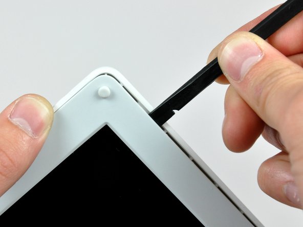
Insert the flat end of a spudger into the gap between the front and rear bezels.
-
Rotate your spudger until it is parallel to the front face of the display.
-
Run the spudger around the perimeter of the display to separate the rear bezel from its retaining clips.
-
-
Cette étape n’est pas traduite. Aidez à la traduire
-
Remove the large piece of tape near the lower right corner of the display.
-
-
Cette étape n’est pas traduite. Aidez à la traduire
-
Remove the single screw inserted through the piece of EMI tape near the bottom edge of the display (it's the first of the two clutch cover screws).
-
Use the tip of a spudger to remove the small washer under the screw you just removed.
-
-
Cette étape n’est pas traduite. Aidez à la traduire
-
Peel the aluminum/EMI tape as one piece off the cast aluminum frame of the clutch hinges.
-
-
Cette étape n’est pas traduite. Aidez à la traduire
-
Remove the pieces of readily removable tape from around the perimeter of the display.
-
-
Cette étape n’est pas traduite. Aidez à la traduire
-
Remove the piece of aluminum tape near the center of the LCD cover.
-
Peel back the piece of tape securing the display data cable ground loop to the thin steel LCD cover.
-
-
Cette étape n’est pas traduite. Aidez à la traduire
-
Remove the two Phillips screws securing each side of the LCD to the clutch hinge frame (four screws total).
-
-
Cette étape n’est pas traduite. Aidez à la traduire
-
Remove the second of the two Phillips screws securing the clutch cover to the cast aluminum frame of the clutch hinges.
-
-
Cette étape n’est pas traduite. Aidez à la traduire
-
Pull the clutch cover away from the front of the display.
-
-
Cette étape n’est pas traduite. Aidez à la traduire
-
Remove the two pieces of tape over the display data/microphone cables near the lower edge of the display.
-
-
Cette étape n’est pas traduite. Aidez à la traduire
-
Use the tip of a spudger to lift the microphone out of the front bezel.
-
De-route the microphone cable from around the top and side of the display.
-
-
Cette étape n’est pas traduite. Aidez à la traduire
-
Disconnect the display data cable by pulling its connector away from the socket on the LCD.
-
Remove the display data cable from the display.
-
-
Cette étape n’est pas traduite. Aidez à la traduire
-
Remove the two pieces of tape covering the inverter/AirPort cables along the lower edge of the display.
-
-
Cette étape n’est pas traduite. Aidez à la traduire
-
Use the flat end of a spudger to push the backlight connector while gently pulling its cables away from the socket on the inverter.
-
Lift the LCD out of the front bezel and set it aside.
-
-
Cette étape n’est pas traduite. Aidez à la traduire
-
Remove the three Phillips screws securing the reed switch board and the AirPort antenna to the front bezel.
-
De-route the reed switch/AirPort antenna cables around the side of the display.
-
-
Cette étape n’est pas traduite. Aidez à la traduire
-
Gently peel the inverter cable ground strap off the cast aluminum frame of the clutch hinges.
-
While pulling the inverter cable away from its socket on the inverter board, use the tip of a spudger to push the connector out of its socket.
-
-
Cette étape n’est pas traduite. Aidez à la traduire
-
Remove the two Phillips screws securing the AirPort antenna to the front bezel.
-
De-route the AirPort antenna cable along the edge of the display.
-
-
Cette étape n’est pas traduite. Aidez à la traduire
-
If you have a 1.33 GHz 12" G4 iBook, simply remove the Inverter/AirPort cables.
-
For all other models, use the flat end of a spudger to remove the antenna board from the front bezel.
-
Remove the inverter/AirPort cables.
-
-
Cette étape n’est pas traduite. Aidez à la traduire
-
Remove the six Phillips screws securing the clutch hinges to the front display bezel.
-
Lift the clutch hinges off the front display bezel.
-


Annulation : je n'ai pas terminé ce tutoriel.
8 autres ont terminé cette réparation.
