| Title: Hyfrecators | Date: 10-4-2019 |
|---|---|
| By: Birtcher and Conmed File = hyfrecator-guide.doc Rev 1.0 | DISCLAIMER: THIS PROCEDURE PROVIDED "AS IS"AND WITH POSSIBLE FAULTS. USER MUSTVERIFYBEFORE USE. NEITHER PROVIDER NORWEBSITEASSUMESANY RESPONSIBILITYFOR ITS USE. |
Table Caption: This table provides information about hyfrecators, including the title, date of creation, authors, and a disclaimer stating the procedure is provided "as is" and users must verify it before use.
1. General
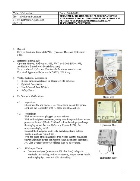
Service Guideline for models 733, Hyfrecator Plus, and Hyfrecator 2000.
2. Reference Documents
Operator Manual, Hyfrecator 2000, P/N 7-900-OM-ENG (1998, Available at frankshospitalworkshop.com)
Service Manual Hyfrecator Plus (available at medwrench.com)
Electrical Apparatus Subcourse MD0363, U.S. Army
3. Tools / Fixtures / Accessories
- Electrosurgical Analyzer: ex: Dempsey 443 or better.
- Optional Footswitch.
- Hand Control Pencil/Cable
- Safety Tester
4. Performance Verifications
4.1. Inspection
Check unit for any damage; i.e. connectors, knobs, the power cord and the footswitch with its cable and strain reliefs.
4.2. Preliminary
With no accessories plugged in, turn unit on.
With no handpiece connected, verify that the up and down arrow power-set buttons (Model 733 has knob and no display) change the display count. For the Hyfrecator Plus and 2000, the maximum display is 30.
Connect the handpiece and verify that its up/down buttons function as above (skip if 733).
With the blade of the handpiece free, verify that the handpiece power activation button activates the unit, noting the alert tone. AC Line Leakage acceptable if less than 50 microamps.
4.3. RF Output Check
- Connect analyzer (wattmeter / 500 ohm load) to bipolar terminals. According to the user manual, output power should track display by 1 watt +/- 10% of reading.
Model 733
- Alternate Method: when the movable lead is in the 'HI' socket, and the analyzer connected between chassis and the pencil tip, power should range from 1 - 30 watts.
- Optional Check: Connect a 25watt light bulb across bipolar terminals. Light bulb should light at ¾ brightness.
Note: For low power, range is 0 to 15 with increments of 0.1 up to 5 watts (note the decimal point). Beyond 5, increment is one.
4.4. Neutral/Patient Plate/ Return Electrode
Note: The Hyfrecator 2000 is the only version of this device to include a jack for a patient plate connection. All units internally connect the return lead of the RF output transformer to chassis ground.
4.5. Calibration
See Service manual.
