Cette version peut contenir des modifications incorrectes. Passez au dernier aperçu vérifié.
Ce dont vous avez besoin
-
Cette étape n’est pas traduite. Aidez à la traduire
-
From the bottom of the unit: Slide the 2 latches to the outer edges and remove the battery.
-
-
Cette étape n’est pas traduite. Aidez à la traduire
-
Completely loosen the 6 captive screws from the rear access panel, unsnap and remove the panel.
-
Completely loosen the 1 captive screw from the cable TV card cover, unsnap and remove the cover.
-
-
Cette étape n’est pas traduite. Aidez à la traduire
-
Remove the 2 retaining screws from the magnetic hard drive, slide the drive out of the socket and remove from the unit.
-
Remove the 1 retaining screw from the solid state hard drive, slide the drive out of the socket and remove from the unit.
-
-
Cette étape n’est pas traduite. Aidez à la traduire
-
Remove the 1 retaining screw from the optical drive and slide it out of the unit.
-
-
Cette étape n’est pas traduite. Aidez à la traduire
-
Push the retaining clips on both sides of the DIMM memory cards to release and remove them from the unit.
-
-
Cette étape n’est pas traduite. Aidez à la traduire
-
Gently pry upward on the 2 antenna wires with a plastic pry tool or guitar pick to unsnap them from the wireless LAN card.
-
Remove the 1 retaining screw from the wireless LAN card and remove it from the unit.
-
-
Cette étape n’est pas traduite. Aidez à la traduire
-
Remove the single keyboard retaining screw. This screw and the screw that held the optical drive in place also attach to the back of the keyboard.
-
-
Cette étape n’est pas traduite. Aidez à la traduire
-
Using a plastic pry tool or guitar pick, carefully lift and unsnap the top of the keyboard starting from one of the top corners. Unsnap the sides of the keyboard and carefully move it forward to expose the attached ribbon cable.
-
Push the ribbon cable fastener forward to release the cable, then slide the cable from the socket and remove the keyboard from the unit.
-
-
-
Cette étape n’est pas traduite. Aidez à la traduire
-
From the bottom of the unit: Remove the 8 retaining screws on the hinge side of the chassis.
-
-
Cette étape n’est pas traduite. Aidez à la traduire
-
Move the ribbon cable fastener forward and disconnect the power button cable from the system board.
-
Move the ribbon cable fastener forward and disconnect the status LED cable from system board.
-
-
Cette étape n’est pas traduite. Aidez à la traduire
-
Using a plastic pry tool or guitar pick, carefully unsnap and lift the power button/status LED cover and remove it.
-
-
Cette étape n’est pas traduite. Aidez à la traduire
-
Remove the remaining 12 retaining screws from the bottom of the chassis.
-
-
Cette étape n’est pas traduite. Aidez à la traduire
-
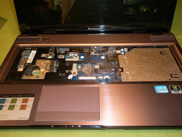
Remove the 2 retaining screws from the top bezel (located where the keyboard used to be).
-
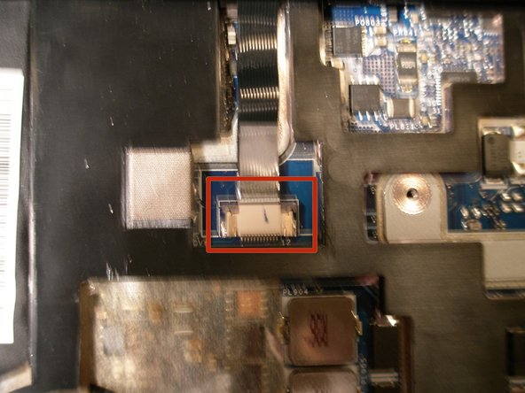
Detach the touchpad and touch inductive panel cables from the system board (there are no fasteners on these cables, just pull them free from the sockets).
-
Detach the LVDS cable from the system board by gently lifting the tape and pulling to the right to unplug the cable.
-
-
Cette étape n’est pas traduite. Aidez à la traduire
-
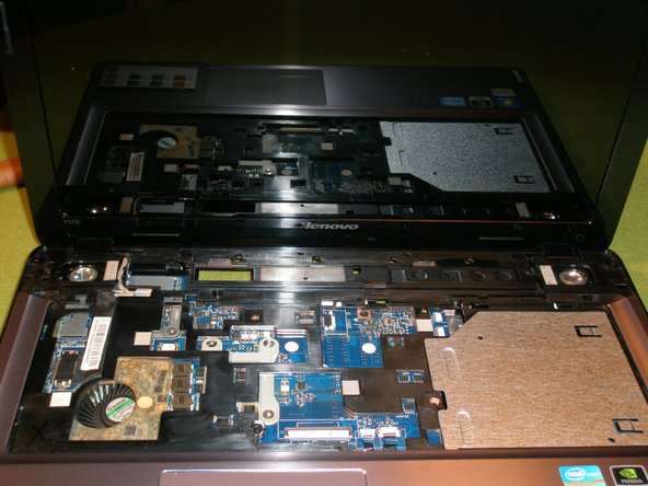
Using a plastic pry tool or guitar pick, carefully unsnap the top bezel and remove it.
-
-
Cette étape n’est pas traduite. Aidez à la traduire
-
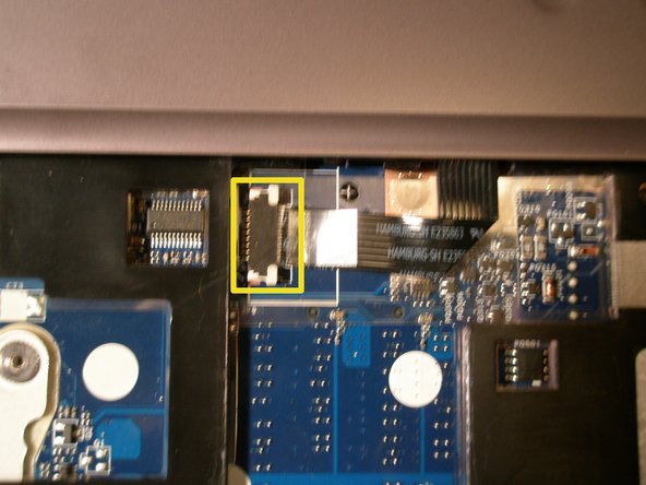
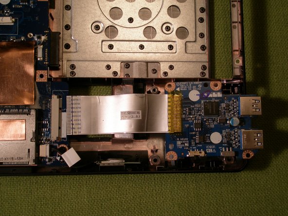
Move the ribbon cable fastener forward and disconnect the USB board cable from the system board.
-
Remove the single retaining screw and lift the USB board from the chassis to remove it.
-
-
Cette étape n’est pas traduite. Aidez à la traduire
-
Unplug the Bluetooth cable from the system board and lift the module from the chassis to remove it.
-
-
Cette étape n’est pas traduite. Aidez à la traduire
-
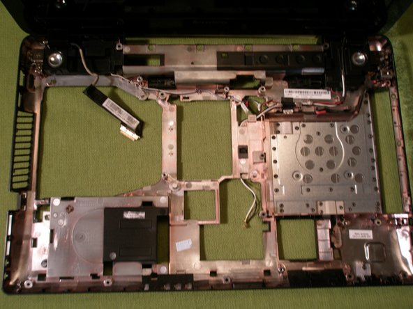
From the bottom of the unit: Unplug the DC power and Speaker cables from the system board.
-
-
Cette étape n’est pas traduite. Aidez à la traduire
-
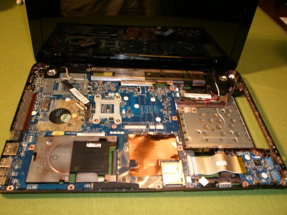
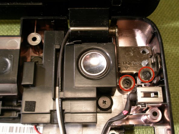
From the top of the unit: Remove the 3 retaining screws on the Motherboard.
-
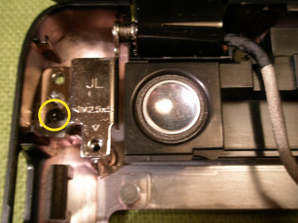
Loosen the screw on the left LCD hinge and carefully lift the Motherboard from the chassis.
-
-
Cette étape n’est pas traduite. Aidez à la traduire
-
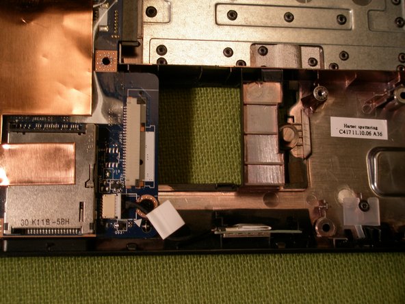
From the bottom of the unit, release the antennae cables from the guides.
-
-
Cette étape n’est pas traduite. Aidez à la traduire
-
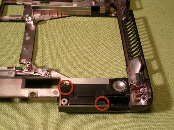
Remove the 3 remaining screws on the LCD hinges and carefully lift the LCD unit from the chassis.
-
-
Cette étape n’est pas traduite. Aidez à la traduire
-
Unplug the fan cable from the Motherboard.
-
Remove the 7 retaining screws and springs on the Heatsink assembly in the order stamped on the Heatsink and lift the assembly free from the system board.
-
Clean the old thermal compound from the CPU and the GPU. Apply a thin film of a quality thermal paste such as "Arctic Silver" when reassembling the unit. Leave all thermal pads in place for reassembly.
-
-
Cette étape n’est pas traduite. Aidez à la traduire
-
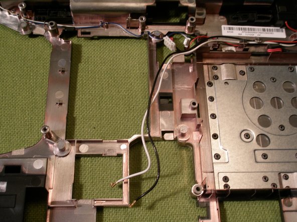
Remove the 4 retaining screws from the speakers, release the speaker cables from the guides and carefully lift the speakers from the chassis to remove them.
-
-
Cette étape n’est pas traduite. Aidez à la traduire
-
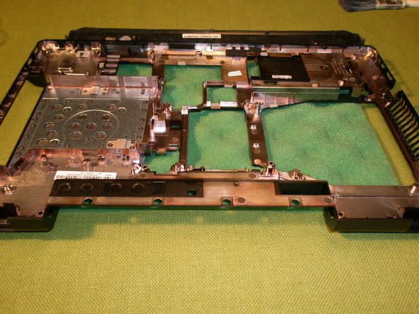
Release the DC Power cable from the guides and carefully lift the DC connector from the chassis to remove it.
-


Annulation : je n'ai pas terminé ce tutoriel.
18 autres ont terminé cette réparation.
3 commentaires
excellent guide - y570 back up and running. thanks.
Can someone list the screws and their sizes? I seem to have put some in the wrong spot/lost a few.
Great Tutorial! Brute force not recommended. Task Failed Successfully!