Cette version peut contenir des modifications incorrectes. Passez au dernier aperçu vérifié.
Ce dont vous avez besoin
-
-
Dévissez les dix vis suivantes fixant le boîtier inférieur au boîtier supérieur :
-
Deux vis Pentalobe P5 de 2,3 mm
-
Huit vis Pentalobe P5 de 3,0 mm
-
-
-
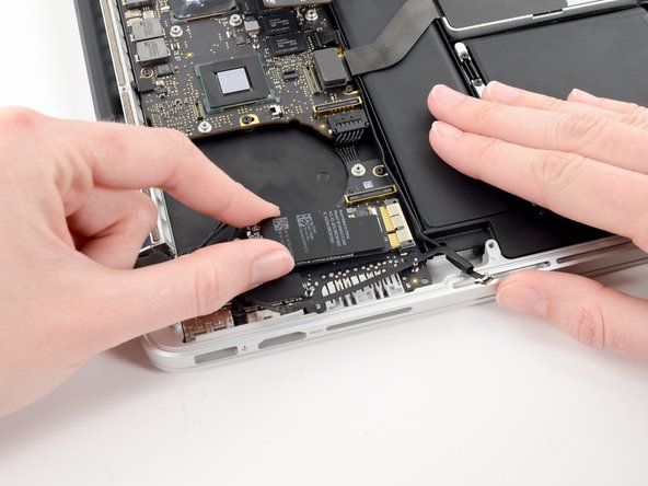
Retirez le cache en plastique couvrant la carte de contact de la batterie.
-
-
-
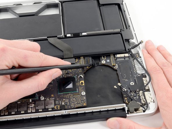
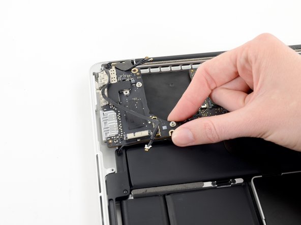
Saisissez l'interposeur avec une pincette.
-
Soulevez l'interposeur et mettez-le de côté.
-
-
-
Cette étape n’est pas traduite. Aidez à la traduire
-
Remove the following screws securing the heat sink to the logic board assembly:
-
One 2.4 mm Phillips #00 screw
-
One 3.4 mm T5 Torx screw
-
Four 2.7 mm T5 Torx screws
-
-
Cette étape n’est pas traduite. Aidez à la traduire
-
Lift and remove the heat sink up off the logic board assembly.
-
-
Cette étape n’est pas traduite. Aidez à la traduire
-
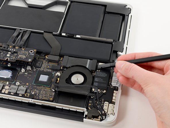
Use the flat end of a spudger to pry the right side of the I/O board data cable connector up off its socket on the I/O board.
-
-
Cette étape n’est pas traduite. Aidez à la traduire
-
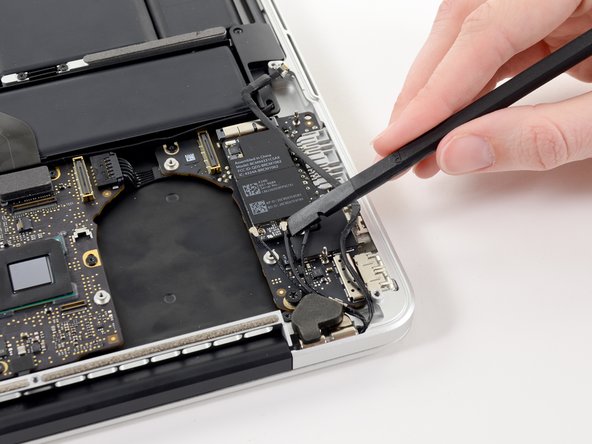
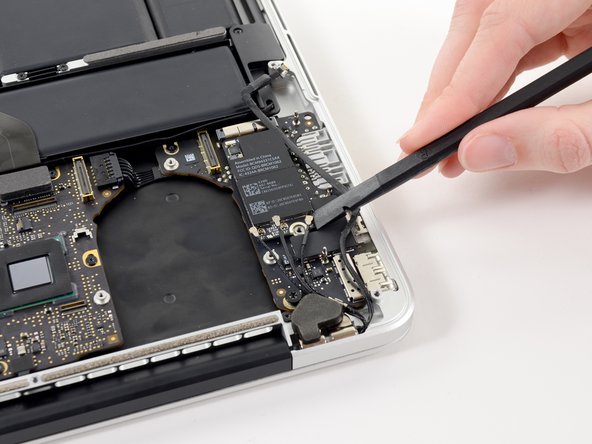
Wedge the flat end of a spudger beneath the left side of the I/O board data cable connector.
-
Gently twist the spudger to disconnect the I/O board data cable connector from its socket on the logic board.
-
-
Cette étape n’est pas traduite. Aidez à la traduire
-
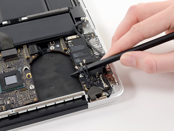
Lift and remove the I/O board data cable from the MacBook Pro.
-
-
Cette étape n’est pas traduite. Aidez à la traduire
-
Use the tip of a spudger to flip up the retaining flap on the right fan ribbon cable ZIF socket.
-
Pull the right fan ribbon cable straight out of its socket on the logic board.
-
-
Cette étape n’est pas traduite. Aidez à la traduire
-
Remove the three 3.1 mm T5 Torx screws securing the right fan to the logic board assembly.
-
-
Cette étape n’est pas traduite. Aidez à la traduire
-
Lift and remove the right fan out of the upper case.
-
-
Cette étape n’est pas traduite. Aidez à la traduire
-
Remove the single 2.7 mm T5 Torx screw securing the AirPort board to the I/O board.
-
-
Cette étape n’est pas traduite. Aidez à la traduire
-
Use the flat end of a spudger to pry and disconnect the three antenna cable connectors from the AirPort board.
-
Connect the long-sleeved cable to the center socket.
-
The short-sleeved cable connects next to the screw.
-
The remaining cable has no sleeve, and connects in the last empty socket, next to the fan.
-
-
Cette étape n’est pas traduite. Aidez à la traduire
-
Move the antenna cables aside, clear of the AirPort board.
-
-
Cette étape n’est pas traduite. Aidez à la traduire
-
Pull the AirPort board straight out of its socket on the I/O board.
-
-
Cette étape n’est pas traduite. Aidez à la traduire
-
Use the tip of a spudger to push the edges of the I/O board power connector straight out of its socket on the logic board.
-
-
Cette étape n’est pas traduite. Aidez à la traduire
-
Pull the I/O board connector straight out of its socket on the logic board.
-
-
Cette étape n’est pas traduite. Aidez à la traduire
-
Remove the following two screws securing the I/O board to the upper case:
-
One 3.5 mm T5 Torx screw
-
One 4.9 mm T8 Torx screw
-
-
Cette étape n’est pas traduite. Aidez à la traduire
-
Carefully pull and remove the I/O board away from its recess in the upper case.
-


Annulation : je n'ai pas terminé ce tutoriel.
6 autres ont terminé cette réparation.
