Cette version peut contenir des modifications incorrectes. Passez au dernier aperçu vérifié.
Ce dont vous avez besoin
-
-
Poussez avec les doigts les deux loquets de déverrouillage de la batterie et retirez celle-ci de l'ordinateur.
-
-
-
Retirez les trois vis identiques Phillips de 2 mm du capot de la mémoire.
-
Soulevez le capot suffisamment pour le saisir et retirez-le en le faisant glisser vers vous.
-
-
-
Retirez les deux vis Phillips 2,8 mm situées près du loquet, dans le compartiment de la batterie.
-
-
-
Soulevez l'arrière du boîtier et à l'aide de vos doigts, libérez progressivement le boîtier par les côtés en allant de l'arrière vers l'avant. Une fois les côtés du boîtier libérés, vous devrez peut-être bouger le boîtier de bas en haut pour libérer la partie avant.
-
Quatre clips en plastique sont disposés au-dessus du logement du DVD et un autre au-dessus, à gauche du capteur infrarouge. Ces clips peuvent être très difficiles à désengager sans mouvement de levier. Ils peuvent également être difficiles à ré-engager lors du remontage.
-
-
-
-
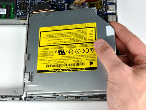
Servez-vous de l'extrémité plate d'un spudger pour débrancher le câble-ruban orange du lecteur SuperDrive de la carte mère. Retirez la bande adhésive si nécessaire.
-
-
-
Retirez les 4 vis suivantes :
-
Deux vis Phillips 3,3 mm argent de chaque côté du lecteur SuperDrive.
-
Une vis Torx T6 4,7 mm argent dans l'angle supérieur gauche du lecteur.
-
Une vis Phillips T6 6,2 mm noire dans l'angle supérieur droit du lecteur.
-
Retirez le lecteur optique de l'ordinateur en le soulevant.
-
-
Cette étape n’est pas traduite. Aidez à la traduire
-
Disconnect the hard drive and ExpressCard connectors from the left side of the logic board.
-
-
Cette étape n’est pas traduite. Aidez à la traduire
-
Disconnect the iSight and display data cables from the logic board by sliding them straight back out of their connectors, removing tape as necessary.
-
-
Cette étape n’est pas traduite. Aidez à la traduire
-
Disconnect the eight indicated connectors by placing a spudger beneath the wired side of each one and lifting up.
-
-
Cette étape n’est pas traduite. Aidez à la traduire
-
Remove the foam bumper from the top of the right hinge of the display.
-
-
Cette étape n’est pas traduite. Aidez à la traduire
-
Remove the silver 9.5 mm T6 Torx screw securing the ground loop in the display data cable to the casing.
-
-
Cette étape n’est pas traduite. Aidez à la traduire
-
Remove the single black 6 mm T6 Torx screw securing the upper portion of the logic board to the lower case.
-
-
Cette étape n’est pas traduite. Aidez à la traduire
-
Peel up the orange Kapton tape securing the right thermal sensor cable to the logic board.
-
-
Cette étape n’est pas traduite. Aidez à la traduire
-
Remove the following 15 screws:
-
One 4.4 mm black Phillips screw to the right of the ram slot.
-
Eight 4.7 mm silver T6 Torx screws securing the logic board to the lower case.
-
One 6.2 mm black T6 Torx screw on the right side of the left fan.
-
Five 9.4 mm silver T6 Torx screws securing the left and right fans.
-
-
Cette étape n’est pas traduite. Aidez à la traduire
-
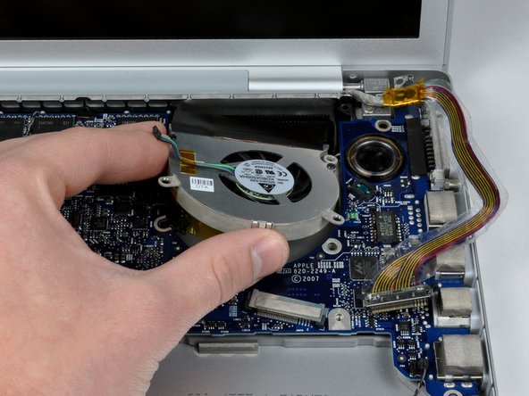
Hold the logic board down with one hand and use your other hand to lift the left fan up from its housing. There is a piece of black tape securing the left fan to the heat sink. Carefully peel this tape up from the heat sink as you lift the left fan up.
-
Lift the right fan up and carefully peel up the tape securing the fan to the heat sink as you go.
-
Remove the right fan from the computer.
-
-
Cette étape n’est pas traduite. Aidez à la traduire
-
Lift up the left side of the logic board and disconnect the gray and black power cable from the bottom of the board.
-
Grasp the logic board at the left side and at the thin section, and rotate the logic board out of the lower case.
-
-
Cette étape n’est pas traduite. Aidez à la traduire
-
Peel back the orange Kapton tape covering the middle thermal sensor.
-
Use a spudger to pry the middle thermal sensor off the heat sink.
-


Annulation : je n'ai pas terminé ce tutoriel.
4 autres ont terminé cette réparation.

2 commentaires
Do you happen to know if MacBook Pro thermal sensors are normally open (NO) or normally closed (NC)? I have a dead A1261 logic board, and one of the thermal sensor connectors came loose from its two wires when I was trying to carefully pry the connector out of its slot in preparation for sending out the logic board for repair or replacement. The connector is so tiny, you literally need a magnifying glass to see what you're doing and it's a challenge to pry it out without accidentally causing damage. Since I already have the dead logic board out of the case, I will replace the thermal sensor before putting a new or repaired logic board back in. I was just curious if a MacBook Pro will boot and run without the sensor connected to the logic board? Presumably this would cause the associated fan to either stay permanently off, or permanently on, depending on whether the sensor is NO or NC, right? Thank you.