Introduction
Follow this guide to replace the screen and battery assembly on your Samsung Galaxy S21+.
This guide is written for the screen and battery assembly. The assembly consists of the screen, battery, and frame together in one part. Be sure you have the right part before you begin the repair.
If your battery is swollen, take appropriate precautions. Before disassembling your device, completely discharge the battery. This reduces the risk of a dangerous thermal event if the battery is accidentally damaged during the repair.
Note: Restoring water resistance after the repair will depend on how well you reapply the adhesive, but your device will lose its IP (Ingress Protection) rating.
Ce dont vous avez besoin
-
-
Insert a SIM eject tool, bit, or straightened paper clip into the SIM card tray hole on the top edge of the phone.
-
Press the SIM eject tool into the SIM card tray hole to eject the SIM card tray.
-
Remove the SIM card tray.
-
-
-
Heat an iOpener and apply it to the bottom edge of the back cover for two minutes.
-
-
-
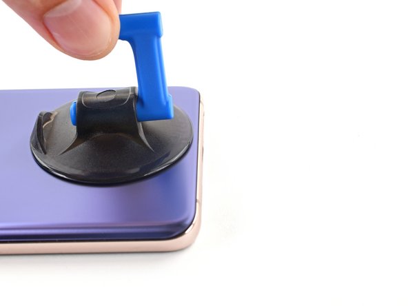
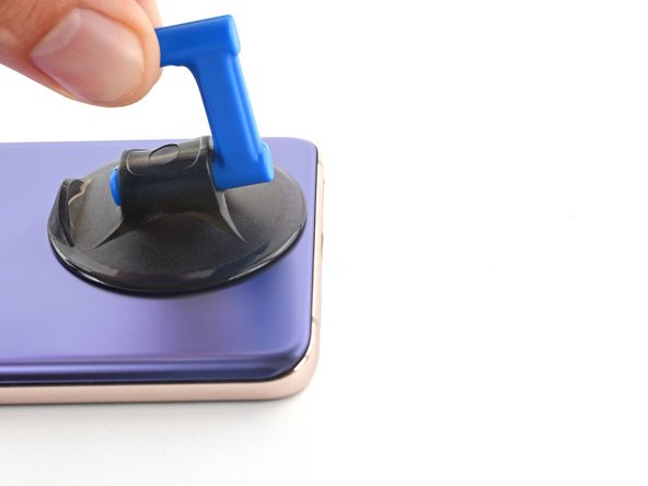
Secure a suction handle to the bottom edge of the back cover, as close to the edge as possible.
-
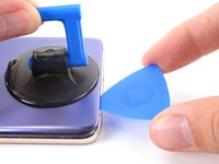
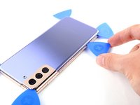
Lift the back cover with the suction handle to create a small gap between the back cover and the frame.
-
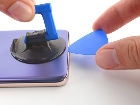
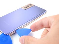
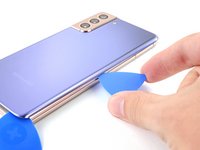
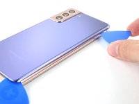
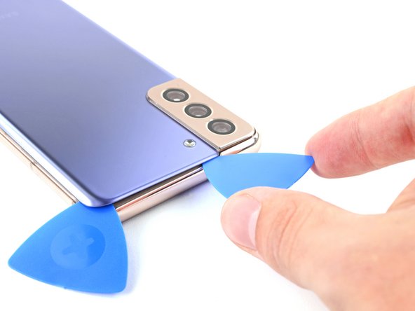
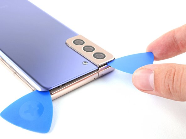
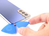
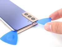
Insert an opening pick into the gap you created.
-
-
-
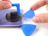
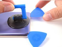
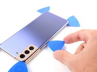
Slide the opening pick to the bottom left corner to slice the adhesive.
-
Leave the opening pick in place to prevent the adhesive from resealing.
-
-
-
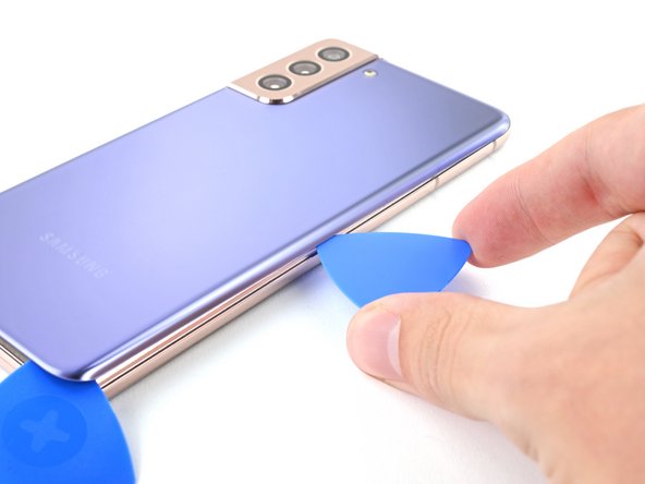
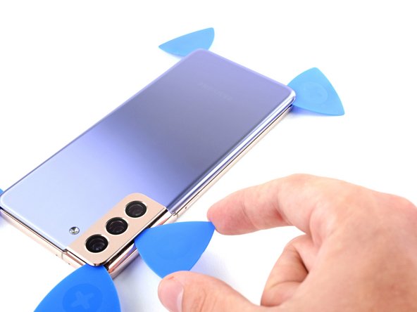
Heat an iOpener and apply it to the right edge of the back cover for two minutes.
-
-
-
Heat an iOpener and apply it to the top edge of the back cover for two minutes.
-
-
-
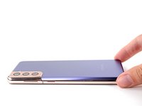
Heat an iOpener and apply it to the left edge of the back cover for two minutes.
-
-
Outil utilisé dans cette étape :Tweezers$4.99
-
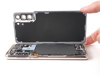
Remove the back cover.
-
This is a good point to power on your phone and test all functions before sealing it up. Be sure to power your phone back down completely before you continue working.
-
Remove any adhesive chunks with a pair of tweezers or your fingers. Use some high concentration (over 90%) isopropyl alcohol to wipe away any adhesive residue.
-
If you're using custom-cut adhesives, follow this guide.
-
If you're using double-sided tape, follow this guide.
-
-
-
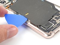
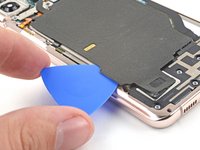
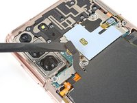
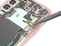
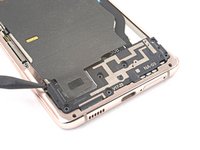
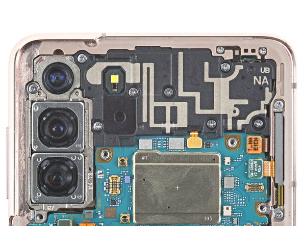
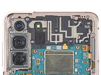
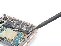
Insert an opening pick underneath the left bottom end of the NFC antenna and charging coil assembly.
-
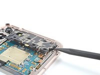
Carefully slide the opening pick along the bottom left edge of the assembly to separate it from the battery.
-
-
-
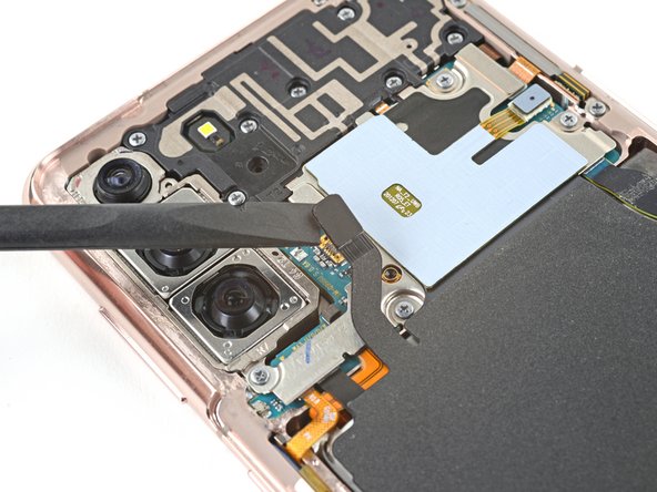
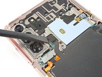
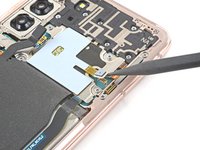
Use a spudger to disconnect the charging coil by prying the connector straight up from its socket.
-
-
-
Use a spudger to disconnect the NFC antenna by prying the connector straight up from its socket.
-
-
-
-
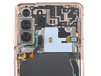
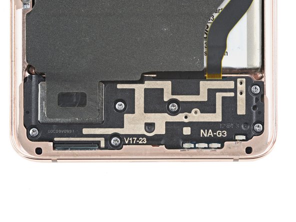
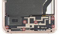
Use a Phillips screwdriver to remove the five 3.9 mm-long screws securing the NFC antenna and charging coil assembly.
-
-
-
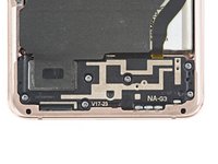
Use a Phillips screwdriver to remove the six 3.9 mm-long screws securing the loudspeaker assembly.
-
-
-
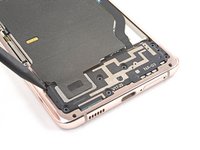
Insert the tip of a spudger between the frame and the upper-left notch in the loudspeaker.
-
Pry up with the spudger to release the loudspeaker from its plastic clips.
-
-
Outil utilisé dans cette étape :Tweezers$4.99
-
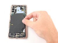
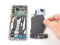
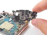
Use a pair of tweezers or your fingers to carefully remove the NFC antenna and charging coil assembly.
-
-
-
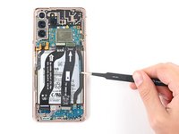
Use a spudger to pry up and disconnect the battery's press connector.
-
-
-
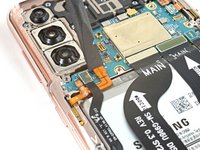
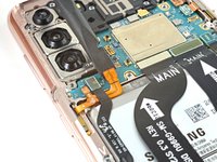
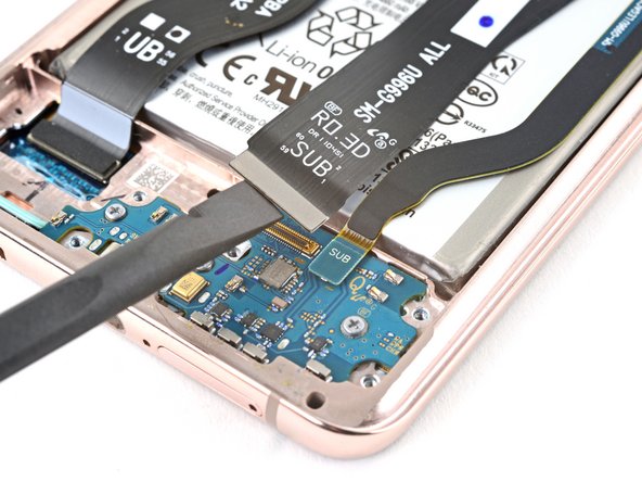
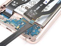
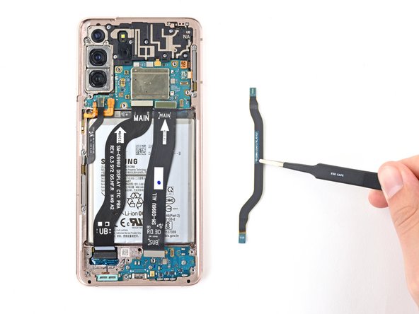
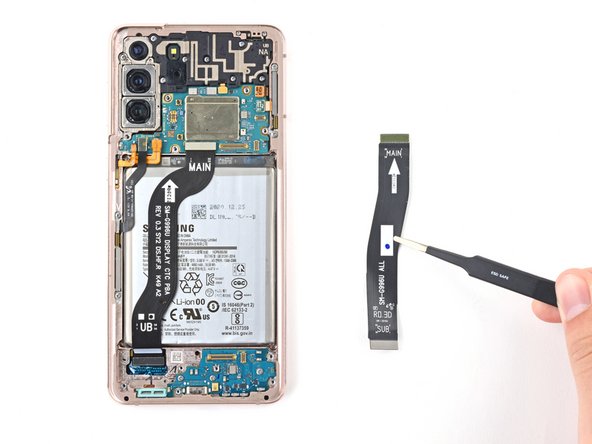
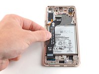
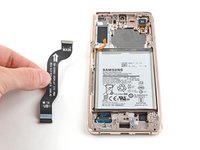
Use a spudger to pry up and disconnect the primary and secondary interconnect cables' press connectors on the motherboard.
-
-
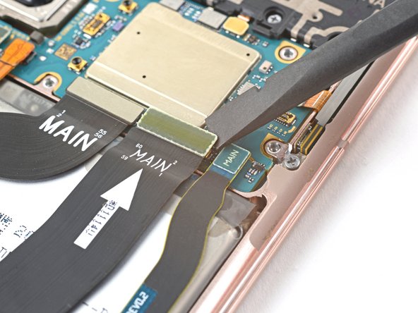
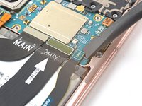
Outil utilisé dans cette étape :Tweezers$4.99
-
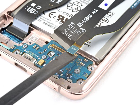
Use tweezers, or your fingers, to remove the interconnect cables.
-
-
-
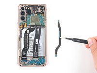
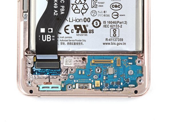
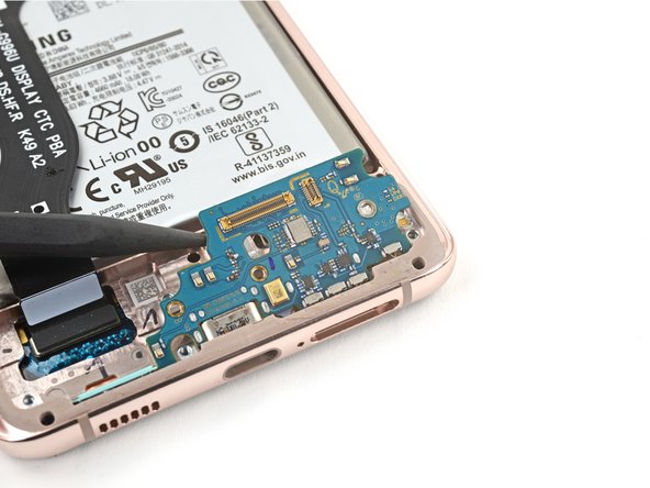
Use a Phillips screwdriver to remove the three 3.4 mm-long screws securing the charging board.
-
-
-
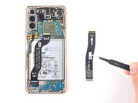
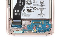
Insert the pointed end of a spudger under the upper left edge of the daughterboard and pry up to release it from its recess.
-
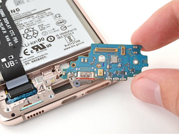
Use tweezers, or your fingers, to pull the daughterboard up and away from the bottom of the device and remove it.
-
-
-
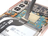
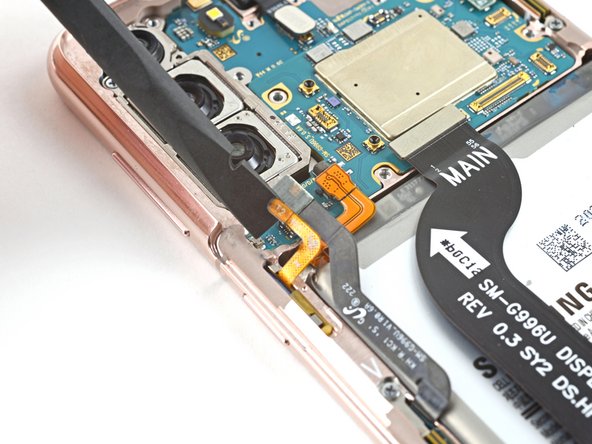
Use a spudger to pry up and disconnect the display cable's press connector.
-
-
-
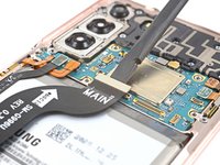
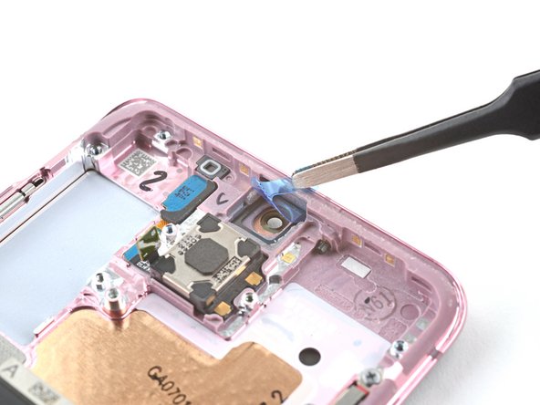
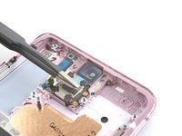
Use the tip of a spudger to pry up and disconnect the earpiece speaker's press connector.
-
-
-
Use a Phillips screwdriver to remove the seven 3.9 mm-long screws securing the earpiece speaker assembly.
-
-
-
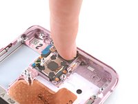
Insert a spudger between the earpiece speaker and the frame.
-
Pry up with the spudger to release the earpiece speaker from its plastic clips
-
Remove the earpiece speaker.
-
-
-
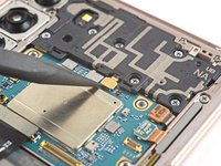
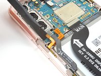
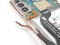
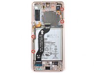
Use a spudger to pry up and disconnect the 5G mmWave antenna's press connector.
-
Repeat for the power button cable's press connector next to it.
-
-
-
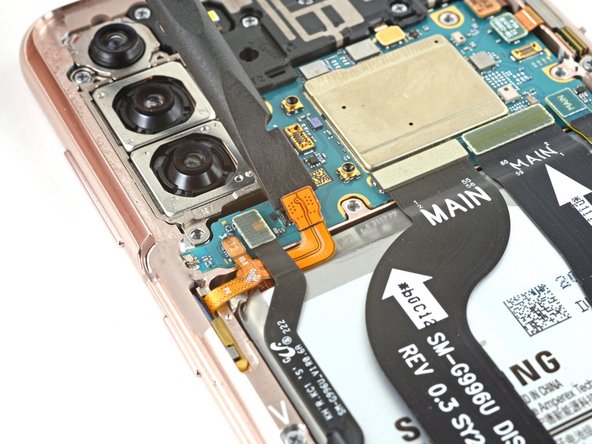
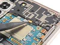
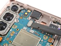
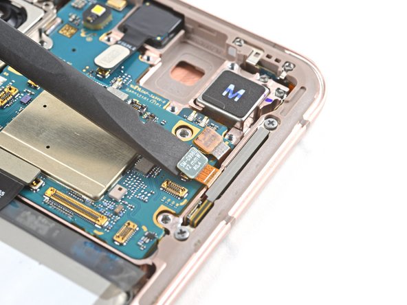
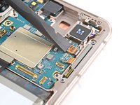
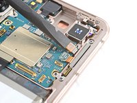
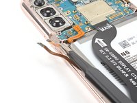
Use a spudger to pry up and disconnect the front camera's press connector.
-
-
-
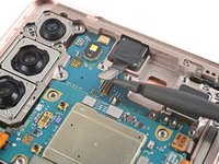
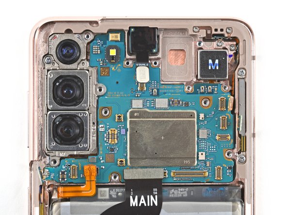
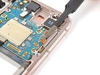
Use a spudger to pry up and disconnect the orange press connector.
-
Repeat for the right 5G mmWave antenna's press connector next to it.
-
-
-
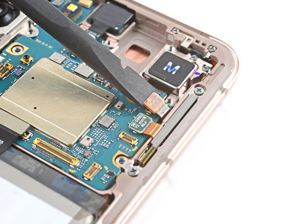
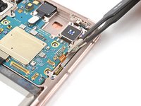
Use a Phillips screwdriver to remove the 3.9 mm-long screw securing the motherboard.
-
-
Outil utilisé dans cette étape :Tweezers$4.99
-
Use tweezers, or your fingers, to gently bend the left 5G mmWave antenna cable away from the frame.
-
Repeat for the power button cable.
-
-
-
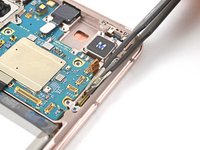
Use tweezers, or your fingers to gently bend the two connectors away from the right edge of the motherboard.
-
-
-
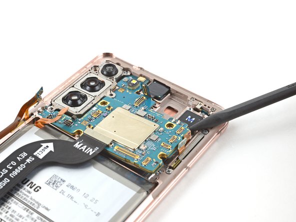
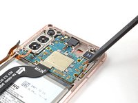
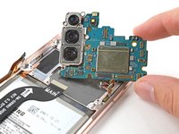
Insert the tip of a spudger between the motherboard and the frame.
-
Pry up with the spudger to release the motherboard from its recess in the frame.
-
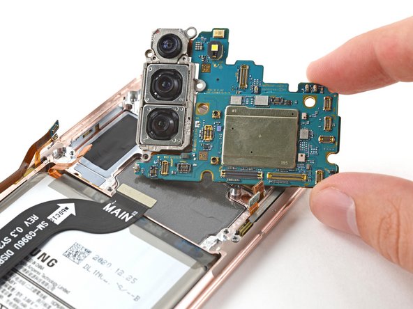
Remove the motherboard.
-
-
-
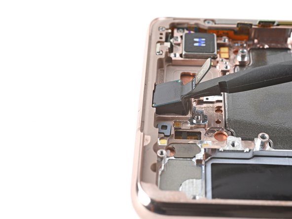
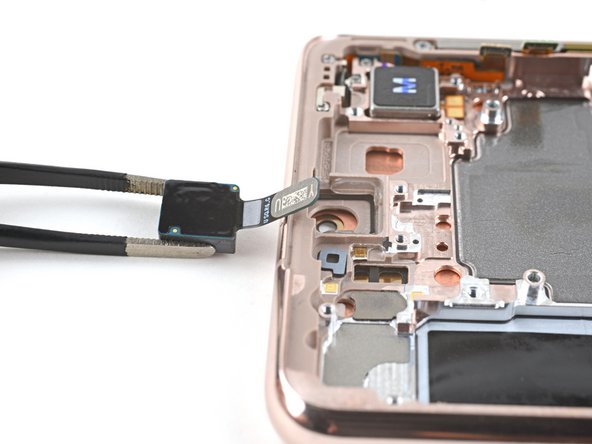
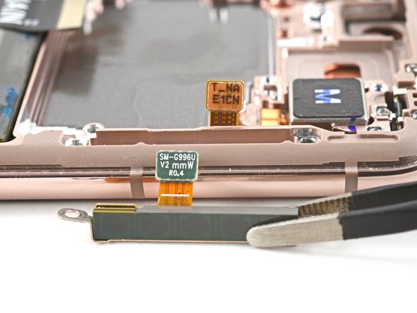
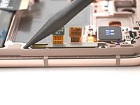
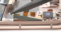
Insert a spudger into the gap between the frame and the front camera.
-
Pry up with the spudger to separate the front camera from the frame.
-
Use tweezers, or your fingers, to remove the front camera.
-
-
-
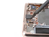
Peel off the front camera adhesive from its liner and apply the sticky end to the frame.
-
Use tweezers, or your fingers, to pull on the tab and expose the top layer of adhesive.
-
Insert the front camera and apply pressure to adhere it to the frame.
-
-
-
Use a Phillips screwdriver to remove the four 3.4 mm-long screws securing the 5G mmWave antennas.
-
-
-
Use the point of a spudger to pry up on the right 5G mmWave antenna bracket's bottom screw tab.
-
Use tweezers, or your fingers, to remove the right 5G mmWave antenna.
-
-
-
Use the point of a spudger to pry up on the left 5G mmWave antenna bracket's bottom screw tab.
-
Use tweezers, or your fingers, to remove the left 5G mmWave antenna.
-
-
-
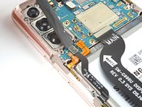
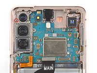
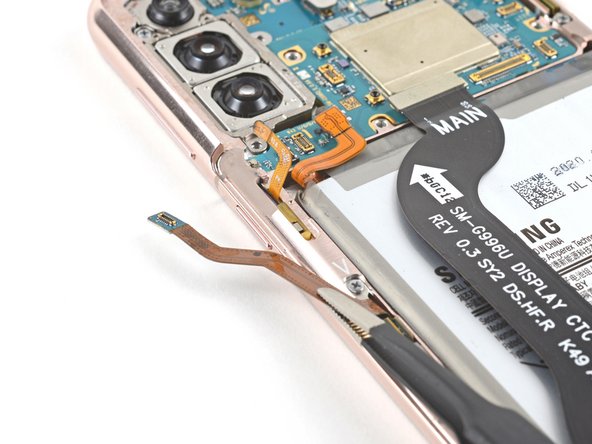
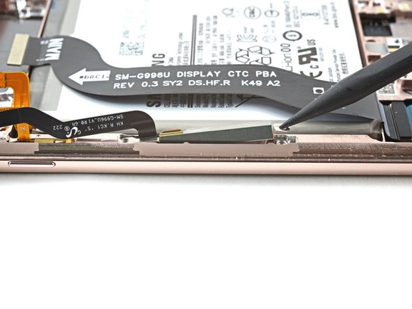
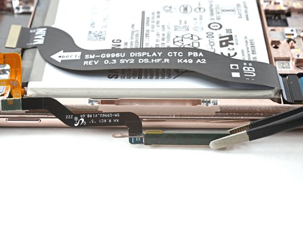
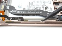
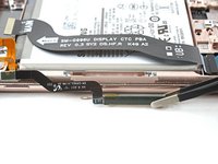
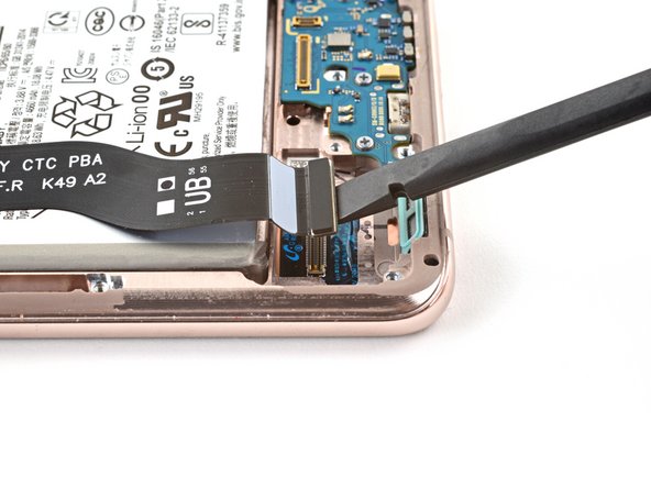
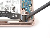
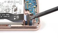
Use a spudger to pry up and disconnect the display cable's press connector near the bottom of the device.
-
-
-
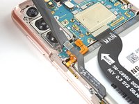
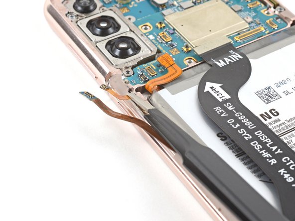
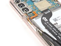
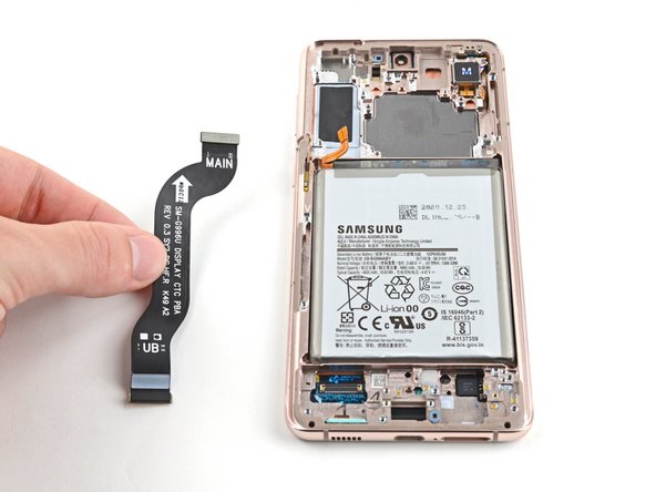
Use tweezers, or your fingers to remove the display cable.
-
-
-
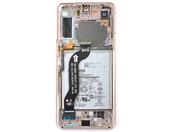
You're now left with the screen and battery assembly.
-


To reassemble your device, follow these instructions in reverse order.
Take your e-waste to an R2 or e-Stewards certified recycler.
Repair didn’t go as planned? Try some basic troubleshooting, or ask our Answers community for help.
To reassemble your device, follow these instructions in reverse order.
Take your e-waste to an R2 or e-Stewards certified recycler.
Repair didn’t go as planned? Try some basic troubleshooting, or ask our Answers community for help.
Annulation : je n'ai pas terminé ce tutoriel.
11 autres ont terminé cette réparation.


2 commentaires
The iFixit IOpener is way to thin for this job unless you work maybe a single side at a time. I ended up using a hair dryer. On my phone the power button side was the easiest side to start on. The suction cup didn't help me much. Do not push it, especially around the camera lens, I cracked my back cover because of impatience. Pretty simple operation once the back cover was off. The Samsung "kit" has extra stuff that's not really needed. Overall, excellent directions, Thanks Alex!!
The first time I did this was about a year ago and the whole set of instructions it was less than 1/2 the time and way easier. I also used a hair dryer but the first time was a bummer. this second time now it was pretty easy and split apart nicely. I think after you already did it once helped a lot. the instructions were precise. It helped me a lot by reading all the instructions a few times thru and the project went as nice as anyone could ask for. Thanks Alex !very nice job I'm 67 yrs old and it was a Breeze.