Ce dont vous avez besoin
-
Cette étape n’est pas traduite. Aidez à la traduire
-
This is it. A Sony BD/CD/DVD player, A/V receiver, amplifier and tuner, all in a PS3 Super Slim-looking device! Will all of these functions make it difficult to repair? Let's see!
-
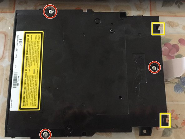
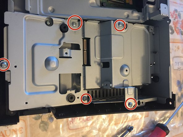
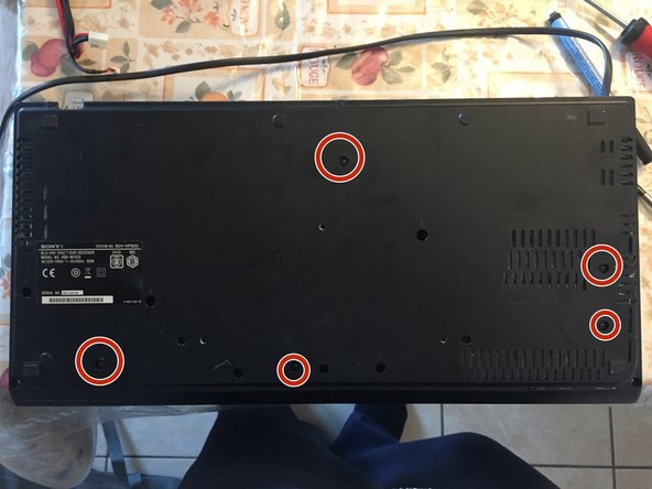
Remove the seven PH1 screws marked with the circle under the player (they're marked with two half arrows on the device).
-
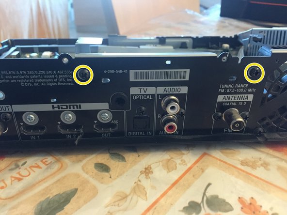
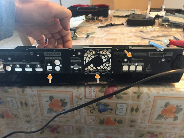
On the back of the device, remove the five PH1 screws marked in yellow (they're the same as the ones in the bottom).
-
-
Cette étape n’est pas traduite. Aidez à la traduire
-
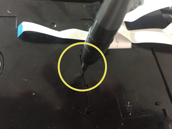
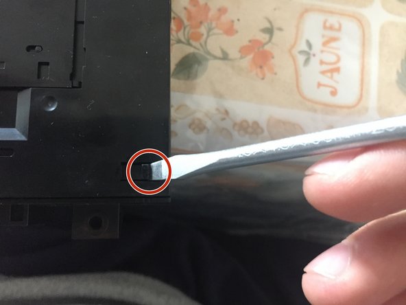
Insert a spudger (or other thin, plastic tools like that) in the small gap between the base and the top. Rotate it like in the picture and slide it across the side. You'll encouter some resistance where the clips are, it's normal.
-
Do the same for the front...
-
...and for the other side.
-
-
Cette étape n’est pas traduite. Aidez à la traduire
-
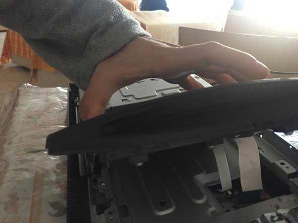
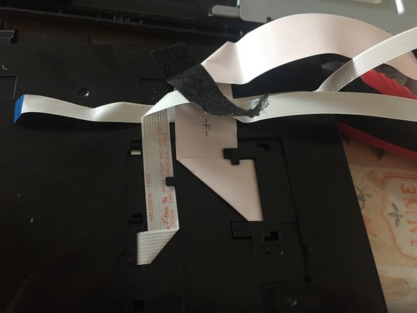
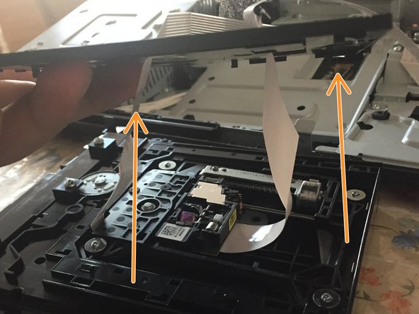
Lift the top cover about 5 cm (2 in) and place it in front of the device, with the curved side on the table.
-
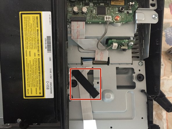
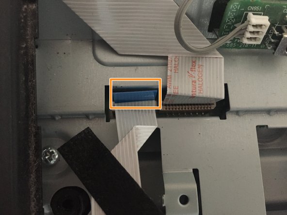
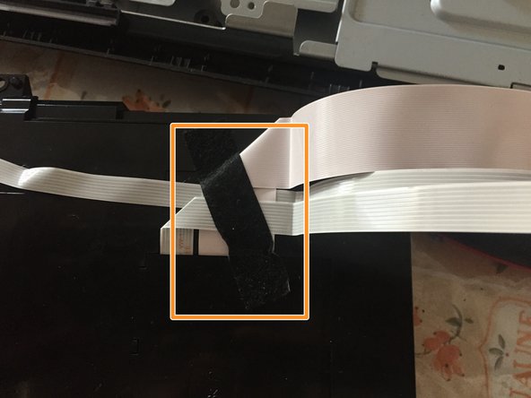
Gently, remove the black felt tape.
-
Remove the touch keys's cable.
-
-
Cette étape n’est pas traduite. Aidez à la traduire
-
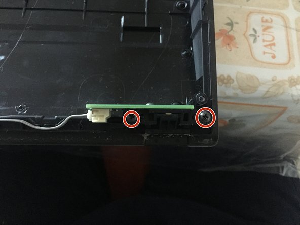
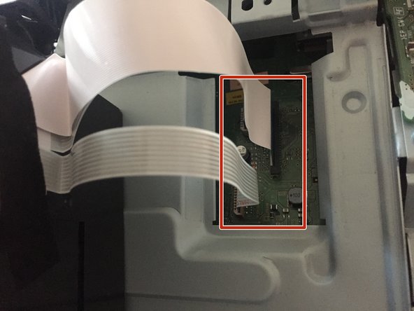
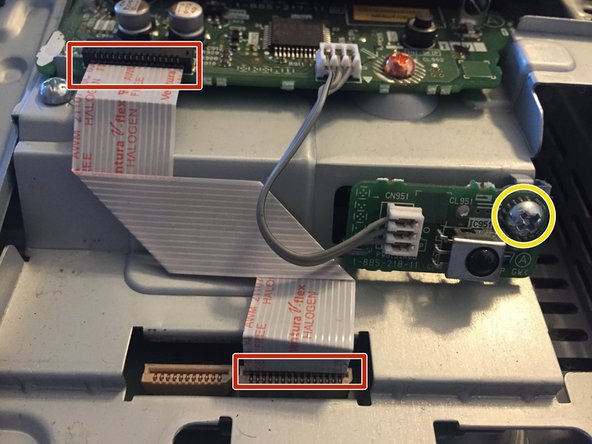
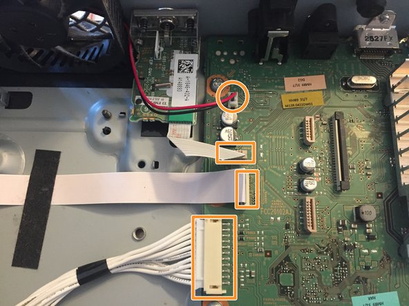
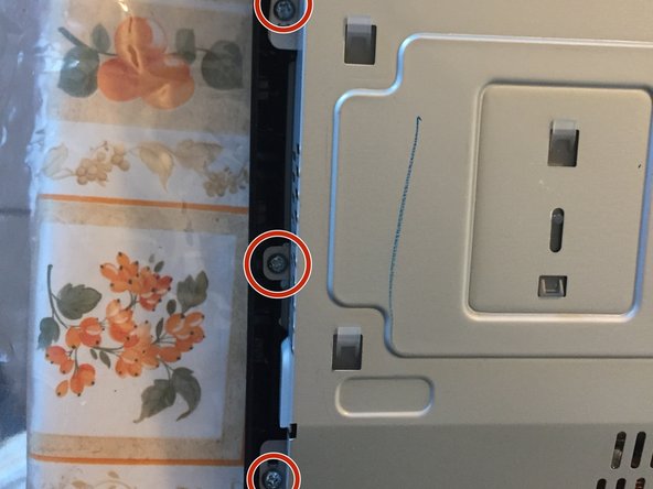
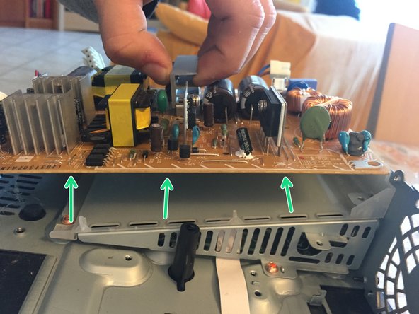
Remove the two PH1 screws.
-
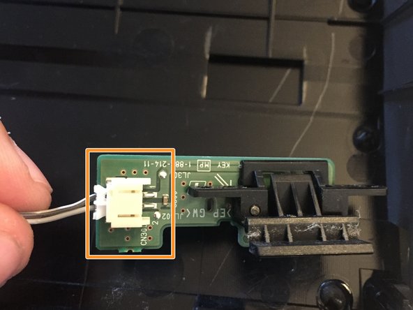
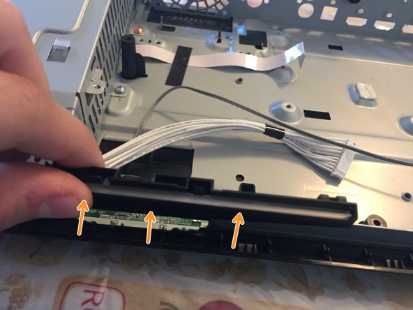
Remove the cable.
-
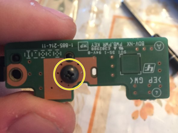
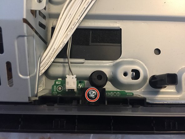
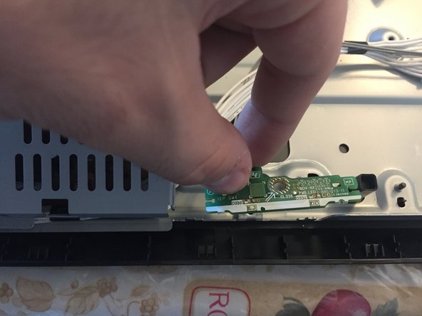
Remove the single PH1 screw and detach the board from the plastic.
-
-
Cette étape n’est pas traduite. Aidez à la traduire
-
Now, back to the main device!
-
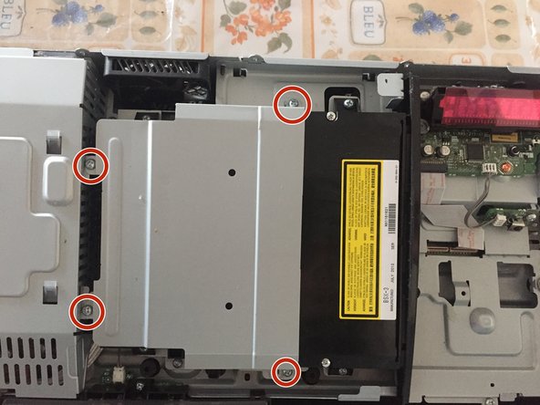
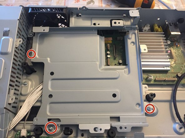
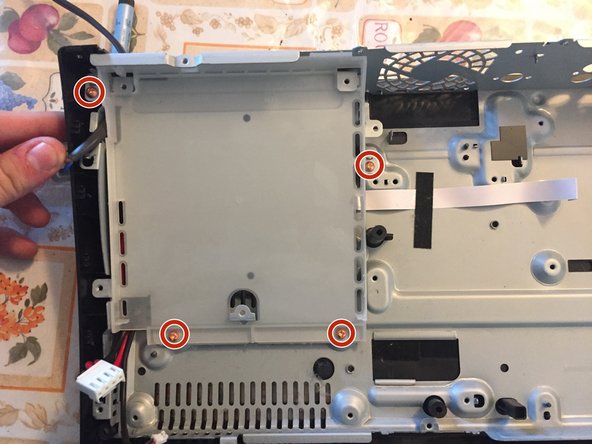
Remove the four PH1 screws and lift the shield out.
-
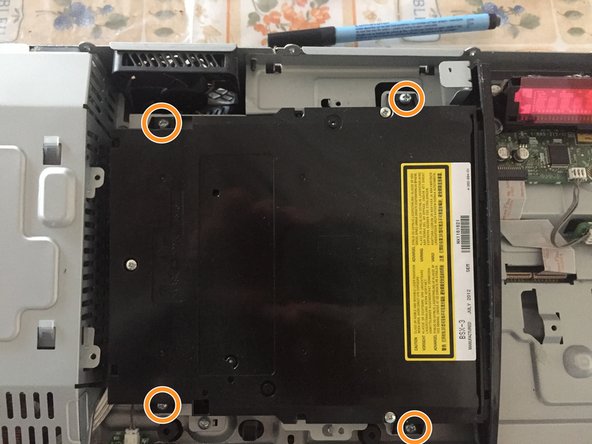
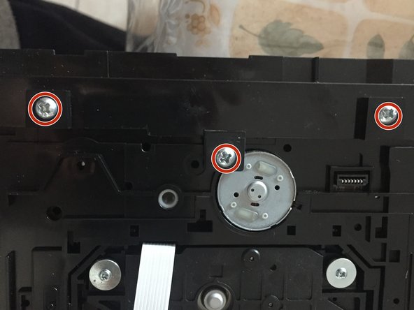
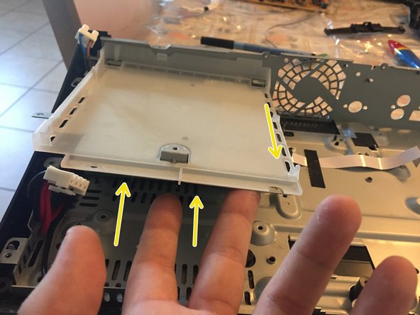
Remove the four PH1 screws (identical to the other four).
-
Gently rotate the optical drive 90 degrees.
-
-
Cette étape n’est pas traduite. Aidez à la traduire
-
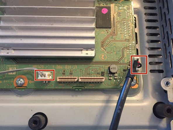
Remove the three cables.
-
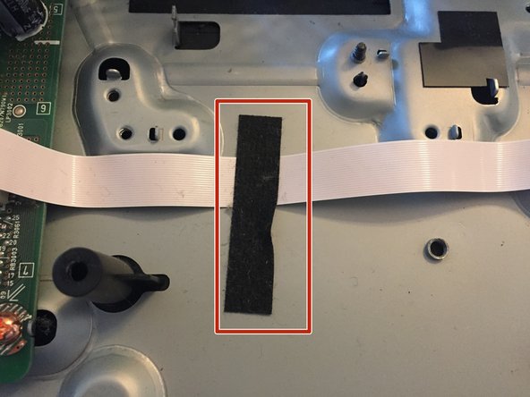
Remove the black felt tape
-
Insert a flathead screwdriver in the gap between the lower part of the optical drive and the little panel, rotate it and remove the panel.
-
-
Cette étape n’est pas traduite. Aidez à la traduire
-
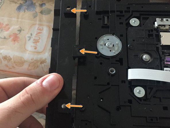
Gently remove the cables from their plastic support tabs.
-
Insert a flathead screwdriver itn the hole near the L-shaped part. slightly rotate it downwards and slide the entire bottom of the drive right until it stops.
-
Lift the cover while being careful not to break the cables.
-
-
Cette étape n’est pas traduite. Aidez à la traduire
-
Remove the three PH2 screws.
-
Slide the inlet to remove it.
-
-
-
Cette étape n’est pas traduite. Aidez à la traduire
-
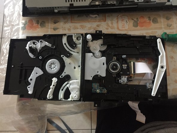
If you have a stuck disc, this is the step you are looking for!
-
Remove the three PH1 screws.
-
(I forgot to take the photo...) Insert a spudger (or similar) in the gap between the two parts of the drive and slide it along the corners. Around the yellow squares there are two clips which will pop when you slide the spudger.
-
-
Cette étape n’est pas traduite. Aidez à la traduire
-
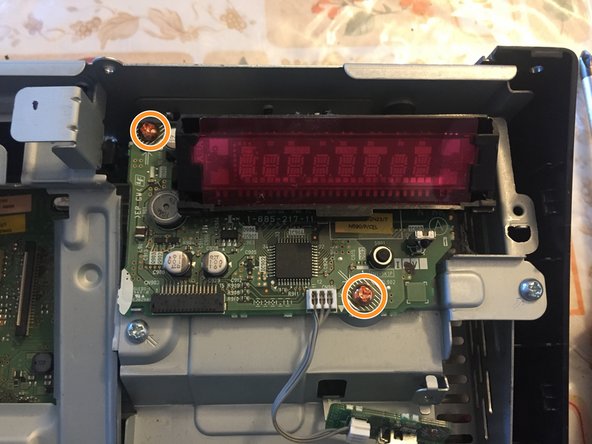
In the main unit, remove the display cable...
-
...the IR sensor PH2 screw...
-
...and the two PH2 orange screws.
-
Lift the display out of the unit.
-
-
Cette étape n’est pas traduite. Aidez à la traduire
-
Remove the five PH2 screws (marked in the shield with double half arrows).
-
At the back, remove the single PH2 screw.
-
Lift the shield out.
-
-
Cette étape n’est pas traduite. Aidez à la traduire
-
Remove the three PH2 screws.
-
At the back of the device, remove the two PH2 screws.
-
Lift the shield out.
-
-
Cette étape n’est pas traduite. Aidez à la traduire
-
Remove the LED cable (grey) and side USB (black, fat).
-
Remove the fan, antenna, audio and power cables.
-
-
Cette étape n’est pas traduite. Aidez à la traduire
-
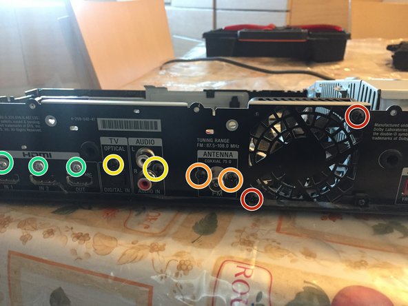
Remove the fan screws and fan...
-
...the antenna connector screws and module...
-
...the audio, optical and (not shown) video screws (all of these are black PH2)...
-
...(silver PH2) HDMI screws....
-
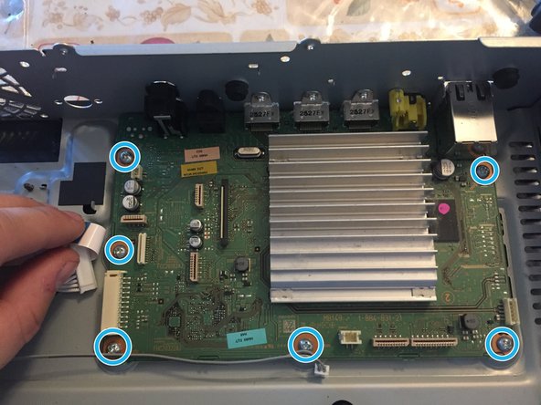
...and finally the six PH2 logic board screws.
-
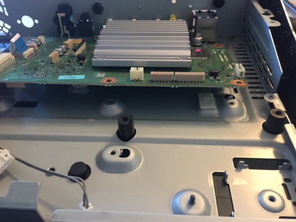
Last but not least rotate the board and slide towards you to remove it.
-
-
Cette étape n’est pas traduite. Aidez à la traduire
-
Remove the single PH2 screw holding the light guide.
-
Lift and remove the light guide.
-
Remove the LED board.
-
-
Cette étape n’est pas traduite. Aidez à la traduire
-
Remove the three PH2 screws on the shield.
-
Remove the shield by lifting it.
-
-
Cette étape n’est pas traduite. Aidez à la traduire
-
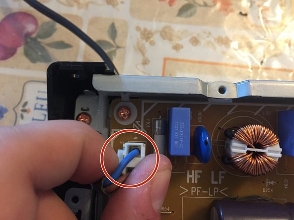
Remove the mains connector by pressing the little lever on it...
-
...then the other two connectors...
-
And the five orange PH2 screws.
-
Grab the power supply unit by the central heat sink and lift it to remove.
-
-
Cette étape n’est pas traduite. Aidez à la traduire
-
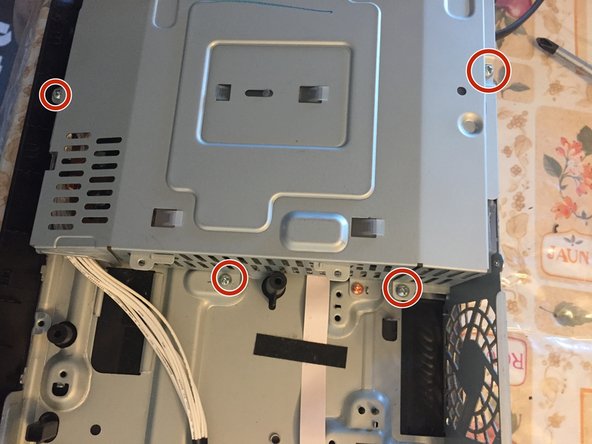
Remove the four orange PH2 screws.
-
At the back, remove the two upper PH2 screws.
-
Rotate the lower edge of the shield and pull it towards you to remove it.
-
-
Cette étape n’est pas traduite. Aidez à la traduire
-
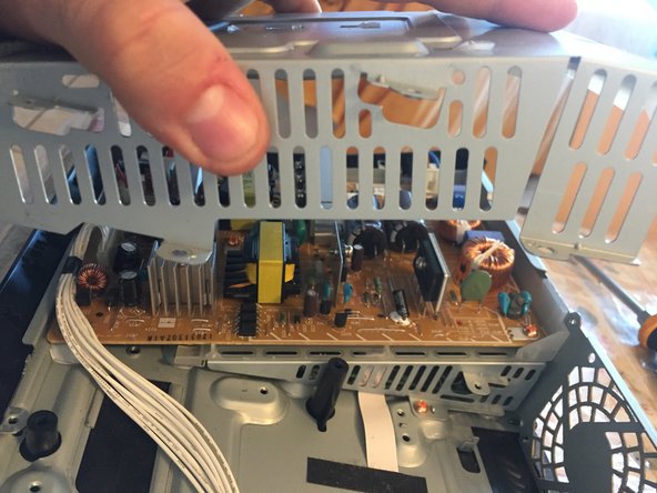
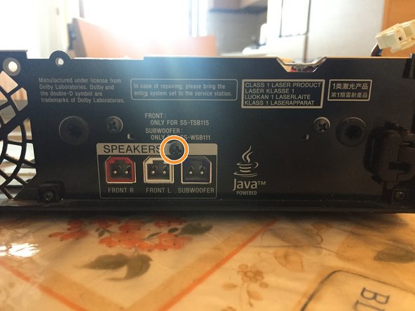
Remove the black felt tape.
-
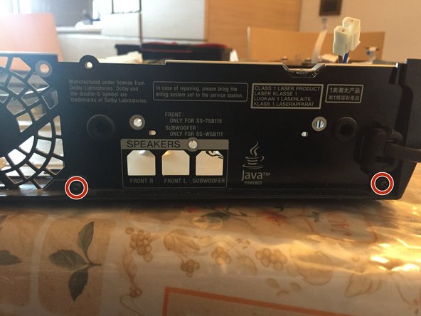
At the back, remove the single black PH2 screw over the speakers connectors.
-
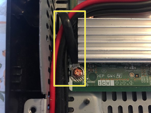
Remove the bottom-left screw with wire-holder.
-
-
Cette étape n’est pas traduite. Aidez à la traduire
-
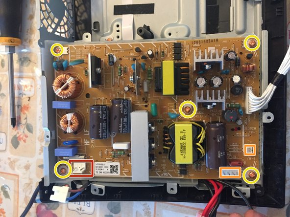
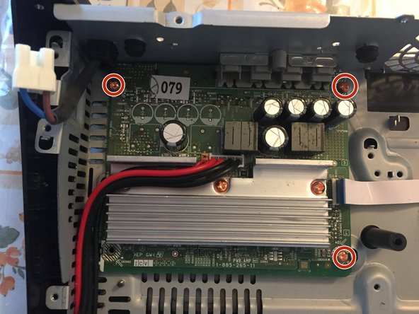
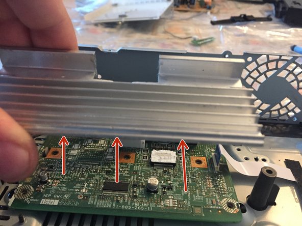
Remove the three orange screws at the corners of the board.
-
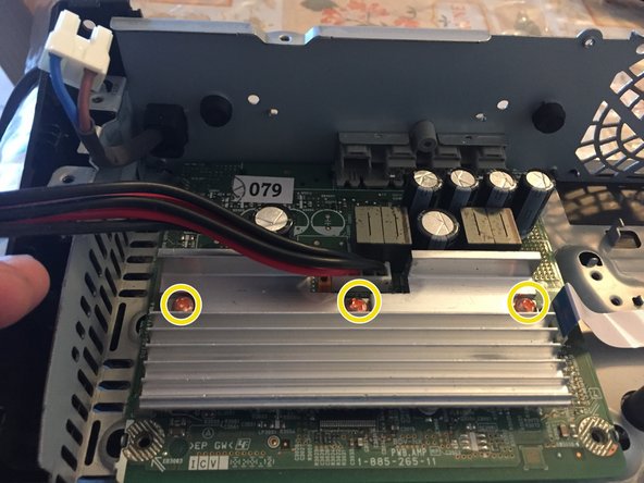
Lift the black and red wires and remove the three orange PH2 screws (they're the longest screws in the device)
-
-
Cette étape n’est pas traduite. Aidez à la traduire
-
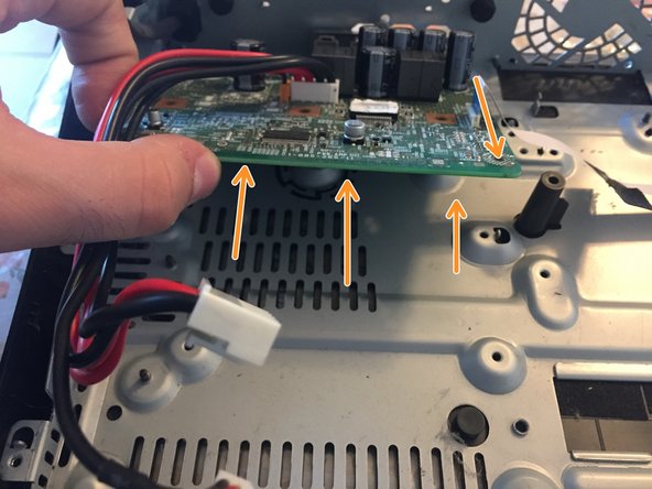
Lift the heat sink...
-
Then rotate and pull towards you the audio board.
-
-
Cette étape n’est pas traduite. Aidez à la traduire
-
Remove the three remaining screws on the lower plastic of the device.
-
-
Cette étape n’est pas traduite. Aidez à la traduire
-
Rotate and lift the frame to remove it.
-
Congratulations, you've torn down the entire device!
-
-
Cette étape n’est pas traduite. Aidez à la traduire
-
I think that this device deserves a 10-/10, because everything is easily removable, there are only five types of screws (and three different sizes) and the cables aren't glued but there's the foam tape holding them.
-
I gave the minus to the score because the IR receiver hasn't a connector but it's soldered and because the touch "keys" are glued onto the upper cover.
-