Introduction
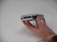
If the microphone or audio jacks are not working on your Sony TCM-450 or TCM-450DV, then this guide will tell you how to replace them. The microphone input and audio output are some of the two most important parts of the TCM-450, as the microphone allows you to record yourself or other objects on the tape recorder and the audio output port allows for the use of headphones.
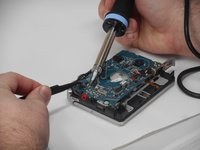
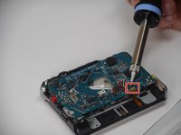
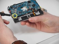
When desoldering the audio output and microphone input you should use some kind of clamp to hold the PCB.
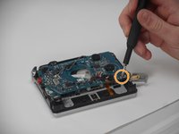
You must be careful when desoldering as there are components that are very close to audio output and microphone input, and you can end up desoldering the components. If this happens you will have to solder the components back on, which can be very difficult even for the most experienced professional. You must be careful when removing the parts as you don't want to rip anything out in the process. The order does not matter, and you do not need to remove one before the other.
Ce dont vous avez besoin
-
-
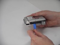
Remove the two 3.5 mm Phillips #00 screws from the bottom of the device.
-
-
-
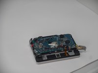
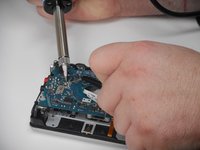
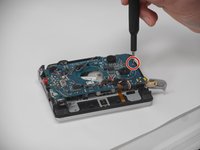
Carefully desolder each connection and gently remove each connected wire.
-
-
-
-
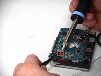
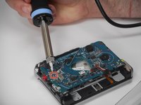
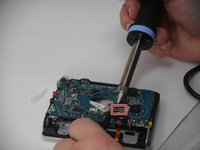
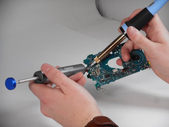
For both the microphone input and audio output, use a desoldering pump for all three solder points. Use the technique here for all of the soldering points.
-
To use the desoldering pump create a suction over the solder point and after the solder has melted press the button on the pump like shown in pictures.
-


To reassemble your device, follow the above steps in reverse order.
Take your e-waste to an R2 or e-Stewards certified recycler.
Repair didn’t go as planned? Try some basic troubleshooting or ask our Answers community for help.
To reassemble your device, follow the above steps in reverse order.
Take your e-waste to an R2 or e-Stewards certified recycler.
Repair didn’t go as planned? Try some basic troubleshooting or ask our Answers community for help.
Équipe

University of Memphis, Team 1-3, Sneed Fall 2024 Membre de l'équipe University of Memphis, Team 1-3, Sneed Fall 2024
UM-SNEED-F24S1G3
4 membres
8 tutoriels rédigés