Introduction
Ce tutoriel vous accompagnera tout au long du processus d'ouverture et de remplacement de la caméra.
Ce dont vous avez besoin
-
-
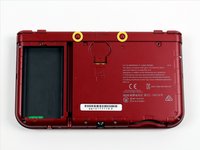
Placez la 3DS à l'envers. Enlevez la cartouche de jeu, écouteurs, chargeur, stylet et tout ce qui pourrait être connecté à la console.
-
-
-
A l'aide d'un tournevis JIS #0, dévissez les deux vis sur l'arrière.
My experience indicates that a JIS #1 is more appropriate here.
Same here, much more appropriate.
-
-
-
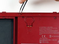
Une fois les vis deserrées , ouvrez le capot arrière.
In order to remove the back cover, slide it down towards you and then pry the cover off.
-
-
-
La batterie est localisée sur la partie gauche de la console - pour l'enlever, utilisez la petite encoche en haut et au milieu puis soulevez la avec un outil pointu non métallique.
Also you should remove any SD card at this point
Does this battery work on a NEW 3DS XL model?
This guide is for the New 3DS XL, which is called the 2015 3DS XL here on iFixit. If you're asking about the 3DS replacement battery advertised in the iFixit store, I believe it works for both new and old models.
The battery is the same and will work on both the new and old models
-
-
-
Avec un tournevis JIS #000, enlevez les six vis de 6mm sur le contour du second couvercle.
I used a #00 instead it works better for a model form 2016
remove the micro Sd card or the shell wont come off and damage the Sd card reader and the connecter
If the J screws are not working, 1.3mm flathead worked for me.
-
-
Outil utilisé dans cette étape :Tweezers$4.99
-
À l'aide d'une pincette, retirez doucement les tampons en caoutchouc situés sur la partie supérieure de la 3DS. Cela révèlera deux autres vis de 6mm. Enlevez également ces vis avec un tournevis JIS #000.
Can the rubber bumpers be replaced once you reassemble the 3DS? I'd really hate to have to take them out and never be able to put them back in, if I'm honest...
Yep, we were able to put them back in quite easily after repeated teardowns! If they ever refused to stay in for some reason, you could always put a little bit of something sticky on them. (I use scrapbooking tape on my laptop's bumpers.)
What happens if I strip one of these screws? How hard would into be to remove them?
very hard. i stripped 4 screws on my new 3ds xl and i haven’t been able to get them out. i even bought the precision screw extrator set and nothing the set sucked.
-
-
-
-
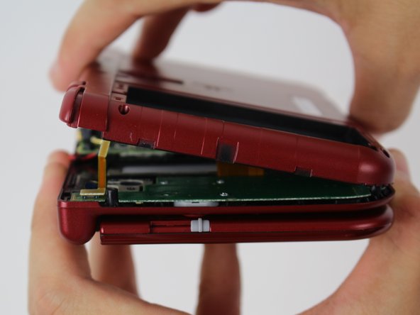
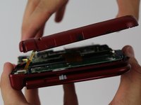
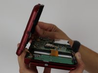
Pour séparer la coque, soulevez la doucement du côté des charnières (de manière à libérer le port pour écouteurs) puis pivotez le vers les charnières pour exposer les cartes électroniques.
I accidentally opened it and broke the ribbon cable to the r and zr buttons by accident. How do I fix it?
You have to replace the whole thing.
-
-
-
Utilisez une paire de pinces pour libérer les deux connecteurs des nappes de boutons L / R / ZL / ZR de la carte mère. Vous pouvez maintenant enlever complètement la coque arrière et la mettre de côté.
I discovered that there is enough clearance to slide the Game Cartridge Slot assembly out without removing the motherboard. Just remove the two connectors going to the Cartridge Slot assembly and take out the 3 screws holding it down. There were two screws that look like they are holding the assembly down, but they are only holes through the assembly and don’t actually hold it down. At least on the Pokemon version, New 3DS XL that I had.
Can confirm, it's leagues easier to do it that way than to go to the trouble of removing the entire motherboard, potentially screwing something up in the process. Thank you so much for sharing this alternative method!
I third this alternative method for D-pad replacement. To add to the previously noted detail, you also need to disconnect a 3rd connector going to the Cartridge Slot assembly, the one going to the D-pad Board itself which is underneath the Cartridge Slot assembly, which is shown at a later step in this guide. Also, I found I needed to loosen the two screws on the motherboard located nearest the Cartridge Slot assembly in order to get enough clearance to slide the assembly out, as there are two plastic guide stands that hold the assembly in place which the motherboard otherwise holds too tightly to pass. Otherwise, incredibly smooth sailing, minimal connectors removed, and my New 3DS LL import model finally has a working left/right again. Thanks everyone!
-
-
-
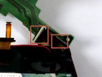
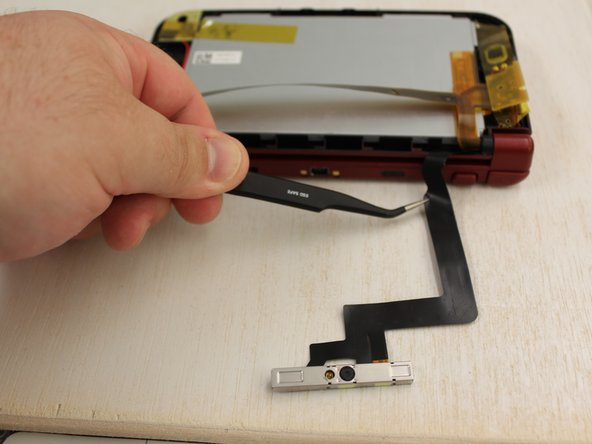
Utilisez une pince à épiler pour relever le petit rabat de verrouillage à charnière afin de déverrouiller le connecteur ZIF fixant le ruban du tampon circulaire.
-
Faites glisser le ruban hors du connecteur ZIF.
Is not the right side, the switch must be pull to the left, otherwise people will brake it.
I suggest removing the joystick first, swing to left side, then lift up on ZIF connector from the right. You’re able to pull ribbon cable out easier from the left at that point w/o breaking it, as I did.
2nd the removing of the joystick first via the two screws and to be careful handling the plastic washer underneath. It’s coated with a Teflon type material to aid in stick movement. also use a finger nail over tweezers any change you get. A nail is less rigid with natural give and less likely to break plastic latches. If it doesn’t open from the end you expect, stop, and try the other side right away. Be gently.
-
-
-
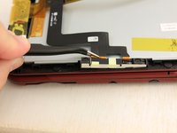
Localisez le connecteur doré avec un câble rouge en haut à gauche de la carte mère. Soulevez le délicatement avec vos doigts vers le haut pour l'enlever.
-
Utilisez une pincette pour débrancher l'unique nappe du connecteur.
MDR j'avais vu cette erreur il y a un petit moment... et vous pouvez ajouter, ne pas casser le connecteur comme sur la photo !
-
-
-
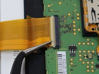
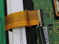
À l'aide d'une paire de pinces, tirez délicatement les cinq nappes marquées hors de leurs connecteurs ZIF sur les bords de la carte mère.
-
Trois des nappes ont des connecteurs à verrou. Utilisez une pince pour les soulever avant d'ôter les nappes.
Hi,
Can you pls inform me the purpose of the topmost red marked ZIF transparent flex cable, I wish to repair my N3DS XL but I am missing this flex cable (for which part is this cable relevant).
Thanks
I don't have the model on me for reference, but if I remember correctly, it's for the bottom screen.
I think it should be noted that the upper most ZIF is incorrectly labelled here as one to remove with tweezers and not to try to open the clamp. I did this recently and have now broken my brand new 3ds. This cable is for the digitizer at the front of the bottom screen. So my touch screen no longer works. I now need to carry out a further repair. Just a heads up.
Accurate. I have to purchase a new digitizer because of this. I tore the conductors in the cable removing it from the ZIF connector. And I’m really very angry that no correction has been made in the almost 9 months since you posted.
Sabs Like Labs, can you please share a picture of your connector ? last time I dismounted one I had no problems with this connector but maby there are different versions ?
Zoe, I don’t suppose you would know what part to search for to replace one of these lock-less friction connectors? Before this article posted I partially broke one of mine thinking it had a lock and would like to replace it. The old one still works but I have to fiddle with it to get a good connection now. The one I broke is nearest to the cartridge socket.
&&^& all those tutoriel now is just break my new 3ds &&^& you internet
I broke my connectors the little gray pieces broke not the touch screen and the joy stick are broken.
I can confirm there are two different versions of the clip. One flips up and just pushes in
As others have mentioned, the topmost red connector HAS A CLAMP that you need to flip up. It seems like the creator of this guide has a 3ds with older board revision. With multiple people already having brought up the issue, the creator should absolutely update this guide to note the differences as others have already broken their devices due to this guide.
Can confirm that the top most connector has a clamp on mine as well. tore the ribbon cable taking it out and now my bottom screen touch screen is unresponsive. also if you are on this guide looking to replace the game card reader, i also found out after trying to replace mine … You DO NOT need to remove the motherboard in order to replace it !
Then digitizer absolutely should be updated to note, I also broke the GREY clamp off, when treying to remove, and bought a new one.
I believe this to be the replacement https://www.amazon.com/dp/B078WQY7N9?psc...
I also ruined the digitizer connector thinking it had a lock (yes, I failed to read the guide correctly). I ordered another motherboard that cost me $100 (ifixit had none in stock, only option on ebay) only to find out it still doesn't work (now for some reason no button nor touchscreen work which doesn't even make sense since they all have different connectors). Please update this guide to point people to just remove the card reader without taking the motherboard off. I could have avoided all this by just replacing the card reader directly.
Wow...ifixit is flat out lying about that top connector. There is no such thing as 2 different board revisions. ALL models have the clamp type connector. If you zoom in you can clearly see the creator has broken off the clamp in the pictures and is misrepresenting it as a friction connector. Unbelievable.
I broke the ZIF connectors by lifting them up, now from not being able to enable wifi to completely unusable. PUT THE WARNING BEFORE THE STEP!
If anybody want an actual, clear video breakdown and reassemble, I recommend this video: https://www.youtube.com/watch?v=cUTVR3Ln...
I had the digitizer problem too; forgot that that connector does have a clamp, and now my digitizer is broken because I tried to reinsert it without unlocking it. I have edited this step so it labels the connector correctly.
-
-
-
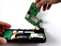
Pivotez doucement la carte mère à 90 degrés vers les charnières pour révéler deux connecteurs ZIF supplémentaires sous la carte.
-
Les deux ont des verrous qu'il faut soulever. Celui de gauche est long et noir; celui de droite est plus court et blanc. Soulevez les clapets, otez les nappes et retirez la carte mère.
9-15 aren't necessary at all. Its a super easy fix step 16 is sufficient.
I think you might be confused; this is a guide for replacing the motherboard, not the entire bottom half of the unit.
The top says this is a guide for the directional pad though
Jimmy -
Oh! Apologies; I didn't realize iFixit duplicated comments for duplicate steps. The message alert directed me to the motherboard replacement guide. Whoops.
Anyway, as I recall, the card reader was more safely and easily removed once the motherboard was out of the way. But I agree that it was likely doable without. Thank you for the input!
Getting the ribbons back in can be a challenge but don’t give up. Pull them taught and try to work at an angle that give you the most length.
Do you know the name of the shorter zif connector, or how to order it? I am talking about the one that is on the botton side of the board,that sometime it is hard to connect the ribbon cable. I think it has like 30 pins. Thank you.
What is the name or how to order the small zif connectors that is on the bottom side of the board, I think it has like 30 pins. Thank you
I just want to swap out lcd screens, what steps can I omit? this is the only bottom screen guide online and so many bricks wtf can’t someone make a video like top lcds there are many.
Update about the commentaries above :
If your goal is to replace something in the top part of the console, steps 9-15 are still necessary as all of the components up there travel through the R hinge to connect to the main board.
- Top screen and Audio/3D cable connect to the back of the motherboard shown at step 15 (screen is the left one shown on the illustration).
- Camera bar connects to the front of the motherboard (step 13, shown as the up-and-rightmost orange connector)
- Wifi antenna connects to the antenna connector (step 12), probably the easiest to replace without disconnecting the motherboard since it doesn't involve rolling up and threading a flat cable through the hinge.
-
-
-
À l'aide d'une tête plate de 1,5, retirez les quatre autocollants en caoutchouc rouge qui se trouvent à l'intérieur du boîtier.
-
Sous le caoutchouc se trouve un adhésif argenté
-
A l'aide d'un tournevis PH00, retirez les vis.
-
-
-
À partir de la charnière, faites glisser la partie extérieure de la coque supérieure afin qu'elle se sépare de la partie intérieure.
-
Le boîtier se détachera et il suffit de le soulever.
In the second picture, you did not list that the removal of two screws were needed, that hold down the boards for the volume/3D controls.
just swype the top case UP side is OK
DO NOT make the same mistake I did. Just slide the top cover forwards, away from the hinge, and it will come off. DO NOT do what this guide says! It will snap the plastic clips that keep the case together and if you don’t want to pay for a full replacement housing it will be impossible to undo!
I will also echo Foam Rais. DO NOT PRY IT! … unless causing unnecessary damage to your stuff is your kink. (I also went in and edited it, but since I has like no rep, I’m assuming it gets reviewed first before going live)
If I’m replacing the top shell, what steps can I skip? It seems like the lower half section with the circle pad and similar bits are unnecessary but I could be wrong.
-
-
-
La caméra doit être lâche, il suffit de la soulever avec précaution.
-
Le câble qui y est attaché doit être facile à retirer de la moitié inférieure de la DS.
-


Pour réassembler votre console, suivez ces instructions dans l'ordre inverse.
Pour réassembler votre console, suivez ces instructions dans l'ordre inverse.
Annulation : je n'ai pas terminé ce tutoriel.
Une autre personne a terminé cette réparation.
Merci à ces traducteurs :
100%


Ces traducteurs nous aident réparer le monde ! Vous voulez contribuer ?
Commencez à traduire ›

Équipe

iFixit, Team 1-1, Weber Winter 2016 Membre de l'équipe iFixit, Team 1-1, Weber Winter 2016
FIX-WEBER-W16S1G1
4 membres
37 tutoriels rédigés
6 commentaires
This doesn't actually show how to get the new camera in, I managed to pull the cable of the old one out but I have no idea how to get the new one through the hinge cover wrapping surround the wires
In some youtube video I saw that guy rolled new camera ribbon cable and got it through the hinge cover.
A whole bunch of steps missing the end. First you have to release the hinge: Remove the circuit board that has the arrow keys (4 screws), remove two plastic pieces immediately above (one black square, when removed a transparent thin piece is visible.
Open hinge to near 180. Using probe or bent tweezers or stiff, thin item, push the hinge pin towards the middle through the narrow opening exposed when the plastic pieces were removed. When it touches the display it's far enough, you may have to slightly flex the hinge to release the pin.
You can now release the other side, with the flex cables going through it and the antenna cable. Feed the 3 flex cables into the slot in the plastic as you release the hinge; once it's clear you can pull them through.
Curl the camera cable (it was on top, and attached on the upper side of the corner of the mainboard) and pull it through the rung and hollow ring.
continues...
"missing at the end" :-)
jesup -
Now reverse with the new cable - curl it gently to get it into the hinge and through the ring, help pull through with tweezers. Now you can start reversing. Note that the hinge pin needs the screen to be open near 180 to slide back into place. Also be careful when reattaching ribbon cables - the display cable (bottom cable of the 3 in the hinge, the longest one) is easy to put in upside down. Take pictures when disassembling. (contacts for this one go down)
I'm replacing my daughters bottom screen and I have a rogue ribbon. I have no clue where it belongs. Any assistance would be appreciated. The ribbon is part is like a L shape with a metal dot on it.