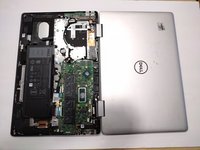
Introduction
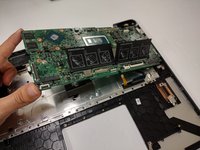
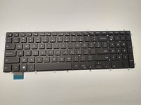
The integrated keyboard is a rather tedious task due to its prerequisites ultimately become a complete disassembly in comparison to most laptops. The keyboard itself is light and has a soft clicking sound when typing. The ability to open the device wide enough to render it as a tablet does leave the keyboard vulnerable to outside elements and potentially damage if not held with care.
Ce dont vous avez besoin
-
-
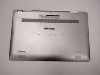
Remove the eight M2 5mm screws that secure the base cover using a Phillips #0 screwdriver.
-
-
Outil utilisé dans cette étape :Tweezers$4.99
-
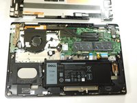
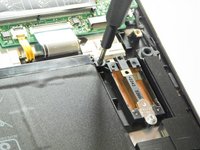
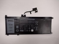
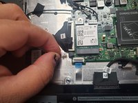
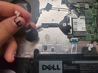
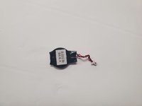
Detach the tab connecting the battery to the system board using your fingers or a pair of tweezers.
-
Peel off the adhesive tab holding the cable to the device.
-
-
-
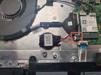
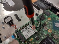
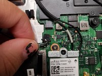
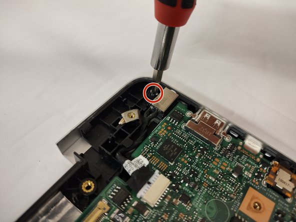
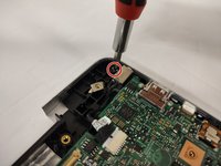
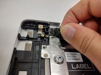
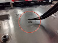
Remove the screw holding down the small bracket for the wireless card using a Phillips #0 screwdriver.
-
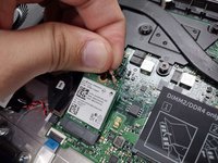
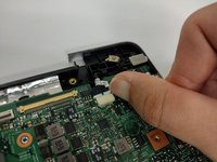
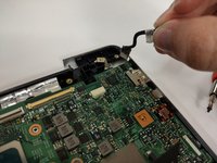
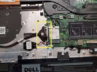
Remove the black wired connection from the port over the black triangle.
-
Remove the wire with the white marking from the port above the white triangle.
-
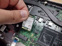
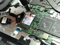
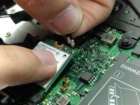
Pull the Wi-Fi card out of its slot.
-
-
-
-
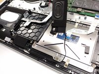
Detach the cable that connects the speakers to the system board.
-
Starting with the speaker on the right hand area of the touch pad, carefully guide the speaker cabling out of the enclosure. You need only to lift upwards.
-
-
-
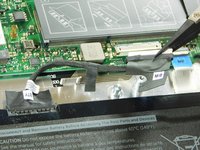
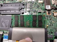
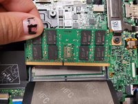
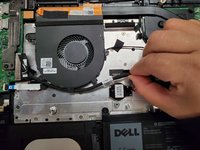
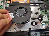
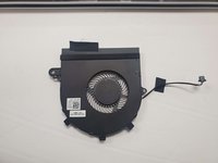
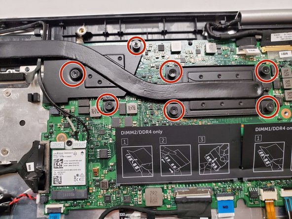
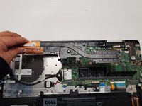
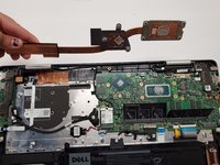
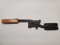
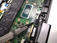
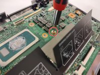
Loosen seven 3 mm captive screws securing the heatsink to the motherboard using a Phillips #0 screwdriver.
-
-
Outil utilisé dans cette étape :Tweezers$4.99
-
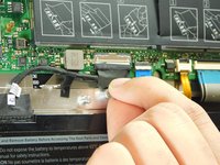
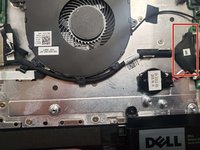
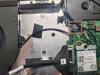
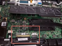
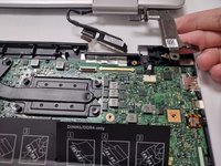
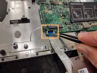
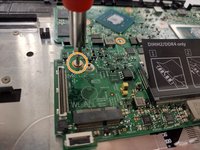
Locate the ribbon cables for the assembly on the right hand side marked "MB1" and "MB2."
-
The "MB1" ribbon is locked with a copper/brass colored handle that must be lifted upwards. Then you can remove the ribbon by pulling it away from the socket.
-
The "MB2" ribbon is locked in its socket with a black latch. Using a non-metallic precision tool (such as tweezers) lift the latch and pull away the MB2 cable.
-
-
-
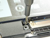
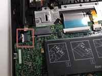
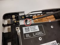
Remove the single 3 mm screw that secures the port using a Phillips #0 screwdriver.
-
Disconnect the cable from the port by gently wiggling and pushing the plug away from the port.
-
Pull the disconnected cable upwards, and the rest of the power port will follow.
-
-
-
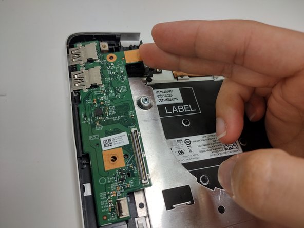
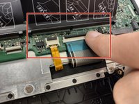
Lift the latch holding down the ribbon cable on the I/O board, then pull it away using the blue tab.
-
Lift the I/O board upwards to remove it from the assembly.
-
-
-
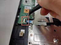
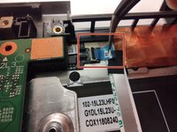
Lift the latch holding down the ribbon cable. Remove the cable away from the port.
-
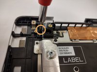
Remove the screw holding down the button in place using a Phillips #0 screwdriver.
-
Grabbing the cushioning of the button, lift it upwards from the assembly.
-
-
-
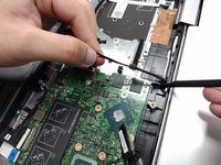
Disconnect all cables from the system board:
-
Keyboard cables with latches
-
HDD cable with latch
-
I/O cable that must be lifted or carefully pried away from the board using a spudger
-
-
-
Lift the latch holding down the ribbon cable connected to the touch pad.
-
Remove the three screws holding down the bracket on the bottom portion of the touch pad using a Phillips #0 screwdriver.
-
Remove the four screws holding down the bracket on the upper portion of the touch pad using a Phillips #0 screwdriver.
-
Remove the bracket on the bottom portion of the touchpad by carefully peeling it away, as it is held by adhesives, then set it aside.
-
-
-
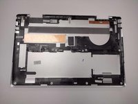
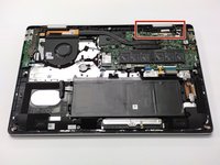
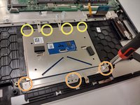
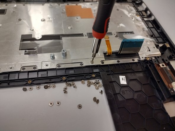
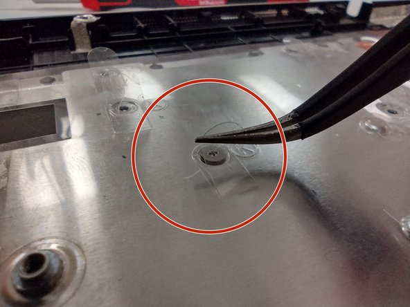
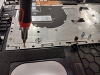
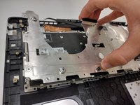
Remove all 32 screws securing the metal plate to the assembly using a Phillips #0 screwdriver.
-
Dell's official manual mentions removing the tape holding the metal plate down. This is optional since you can pick and lift the outlines of small tabs covering the screws of the right hand area of the assembly.
-


To reassemble your device, follow these instructions in reverse order.
To reassemble your device, follow these instructions in reverse order.
Annulation : je n'ai pas terminé ce tutoriel.
Une autre personne a terminé cette réparation.

Équipe

Gateway, Team 1-3, Class Fall 2022 Membre de l'équipe Gateway, Team 1-3, Class Fall 2022
GCC-CLASS-F22S1G3
4 membres
15 tutoriels rédigés
Un commentaire
it has a lot of unnecessary steps that just cost time.
But thanks anyway, saved me a ton of time!