Cette version peut contenir des modifications incorrectes. Passez au dernier aperçu vérifié.
Introduction
Ce tutoriel va vous guider à travers les différentes étapes à suivre pour remplacer une carte mère défectueuse.
Cette carte mère inclus les différents ports situés sur le côté droit du MacBook pro.
Ce dont vous avez besoin
-
-
Poussez avec les doigts les deux loquets de déverrouillage de la batterie et retirez celle-ci de l'ordinateur.
-
-
-
Retirez les trois vis identiques Phillips de 2 mm du capot de la mémoire.
-
Soulevez le capot suffisamment pour le saisir et retirez-le en le faisant glisser vers vous.
-
-
-
Retirez les deux vis Phillips 2,8 mm situées près du loquet, dans le compartiment de la batterie.
-
-
-
Soulevez l'arrière du boîtier et à l'aide de vos doigts, libérez progressivement le boîtier par les côtés en allant de l'arrière vers l'avant. Une fois les côtés du boîtier libérés, vous devrez peut-être bouger le boîtier de bas en haut pour libérer la partie avant.
-
Quatre clips en plastique sont disposés au-dessus du logement du DVD et un autre au-dessus, à gauche du capteur infrarouge. Ces clips peuvent être très difficiles à désengager sans mouvement de levier. Ils peuvent également être difficiles à ré-engager lors du remontage.
-
-
-
-
Servez-vous de l'extrémité plate d'un spudger pour débrancher le câble-ruban orange du lecteur SuperDrive de la carte mère. Retirez la bande adhésive si nécessaire.
-
-
-
Retirez les 4 vis suivantes :
-
Deux vis Phillips 3,3 mm argent de chaque côté du lecteur SuperDrive.
-
Une vis Torx T6 4,7 mm argent dans l'angle supérieur gauche du lecteur.
-
Une vis Phillips T6 6,2 mm noire dans l'angle supérieur droit du lecteur.
-
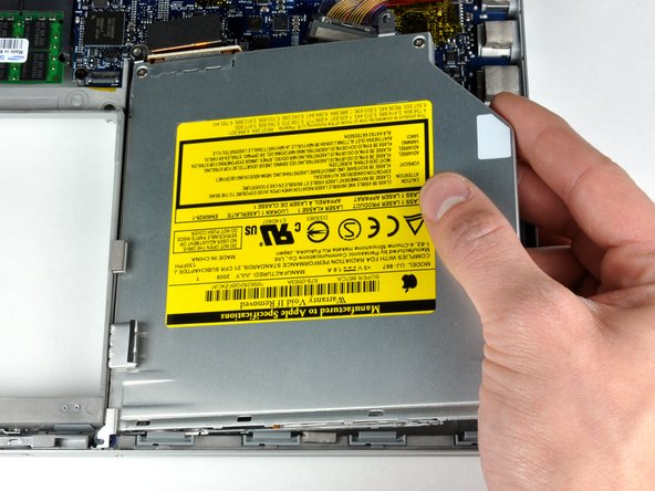
Retirez le lecteur optique de l'ordinateur en le soulevant.
-
-
Cette étape n’est pas traduite. Aidez à la traduire
-
Disconnect the hard drive and ExpressCard connectors from the left side of the logic board.
-
-
Cette étape n’est pas traduite. Aidez à la traduire
-
Disconnect the iSight and display data cables from the logic board by sliding them straight back out of their connectors, removing tape as necessary.
-
-
Cette étape n’est pas traduite. Aidez à la traduire
-
Disconnect the eight indicated connectors by placing a spudger beneath the wired side of each one and lifting up.
-
-
Cette étape n’est pas traduite. Aidez à la traduire
-
Remove the foam bumper from the top of the right hinge of the display.
-
-
Cette étape n’est pas traduite. Aidez à la traduire
-
Remove the silver 9.5 mm T6 Torx screw securing the ground loop in the display data cable to the casing.
-
-
Cette étape n’est pas traduite. Aidez à la traduire
-
Remove the single black 6 mm T6 Torx screw securing the upper portion of the logic board to the lower case.
-
-
Cette étape n’est pas traduite. Aidez à la traduire
-
Peel up the orange Kapton tape securing the right thermal sensor cable to the logic board.
-
-
Cette étape n’est pas traduite. Aidez à la traduire
-
Remove the following 15 screws:
-
One 4.4 mm black Phillips screw to the right of the ram slot.
-
Eight 4.7 mm silver T6 Torx screws securing the logic board to the lower case.
-
One 6.2 mm black T6 Torx screw on the right side of the left fan.
-
Five 9.4 mm silver T6 Torx screws securing the left and right fans.
-
-
Cette étape n’est pas traduite. Aidez à la traduire
-
Hold the logic board down with one hand and use your other hand to lift the left fan up from its housing. There is a piece of black tape securing the left fan to the heat sink. Carefully peel this tape up from the heat sink as you lift the left fan up.
-
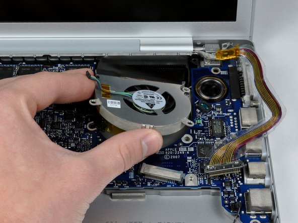
Lift the right fan up and carefully peel up the tape securing the fan to the heat sink as you go.
-
Remove the right fan from the computer.
-
-
Cette étape n’est pas traduite. Aidez à la traduire
-
Lift up the left side of the logic board and disconnect the gray and black power cable from the bottom of the board.
-
Grasp the logic board at the left side and at the thin section, and rotate the logic board out of the lower case.
-
-
-
Relâchez simultanément les onglets de chaque côté de la barrette de RAM. Ces onglets verrouillent la barrette en place et les libérer provoqueront une «pop» de la puce.
-
Retirez la puce directement de son connecteur.
-


Pour remonter votre appareil, suivez ces instructions dans l'ordre inverse.
Pour remonter votre appareil, suivez ces instructions dans l'ordre inverse.
Annulation : je n'ai pas terminé ce tutoriel.
234 autres ont terminé cette réparation.
Merci à ces traducteurs :
100%

Ces traducteurs nous aident réparer le monde ! Vous voulez contribuer ?
Commencez à traduire ›

17 commentaires
In step 15 re: foam bumper. On the reinstall of the foam bumper what do you use to reattach it and hold it in place?
You can use double sided tape, foam or regular scotch,3m to reattach it.
Thank you ifixit! I used this guide to remove and replace my logic board in my early 2008 MBP. I am among the successful (so far) ones who managed to reflow the gpu solder via the oven method. I purchased a few items from you to do the job. I had nothing to lose, so I went for it - and a detailed step by step guide no doubt was key to my success. The Arctic thermal paste was important to the reassembly as was removing all the dust clogging fans and heatsinks. My machine, which has been sitting collecting dust since last summer is humming quietly - I was able to upgrade to Yosemite on this old workhorse and testing it now. Woo hoo!
I recently had to reflow the chipset on my A1226 and then applied new thermal paste.
However, I forgot to remove the plastic tabs at the top of the logic board and they melted from the temperature of the heat gun. Now I cannot screw in the two center top screws on the back cover. First what are those pieces called and how can I get replacements?
They are tiny but apparently have a key function in reassembling the case.
I would appreciate any advice.
Thank you.
Howard U.
I forgot to attach the two bumpers before reassembling my MBP the first time I baked the logic board, so I saved them (for the next time). I needed to do another baking, so I reinstalled them after I was done. I did not have trouble reinstalling the screws as you describe - so maybe some part of the melted bumpers is obscuring the holes?