Introduction
This guide shows how to remove and replace the screen and lens assembly for the Meta Quest 2.
The screen and lens assembly includes the lens housing, screen panels, lens optics, and motion tracking cameras.
Note: You'll need a long PH00 bit or a dedicated PH00 screwdriver to remove some recessed screws.
Ce dont vous avez besoin
-
-
Hold the power button for three seconds to fully turn off your headset.
-
-
-
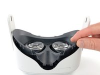
Grasp and pull on the nose section of the facial interface to unclip it from the headset.
-
-
-
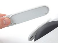
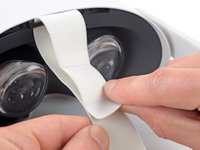
Use your fingers to grasp the right strap near the headset.
-
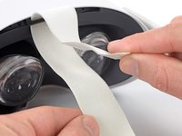
Peel the right strap away from the headset arm to unclip it.
-
-
-
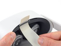
Unthread the top strap from its bracket.
-
Remove the head strap.
-
-
-
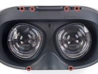
Use a Torx T2 driver to remove the six 3.5 mm‑long screws securing the eyepiece trim.
-
-
-
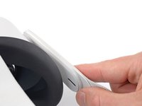
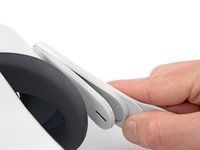
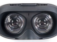
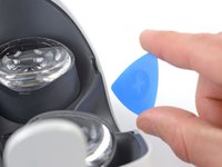
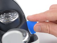
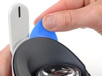
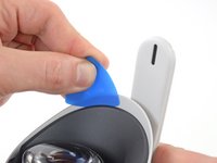
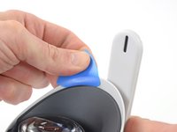
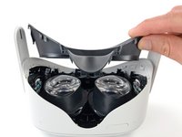
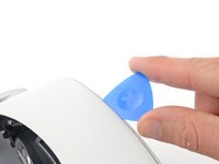
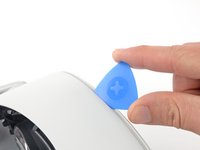
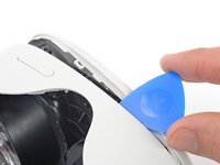
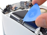
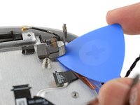
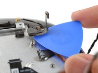
Insert an opening pick into the seam between the eyepiece trim and white outer shell, near the nose cutout.
-
-
-
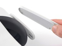
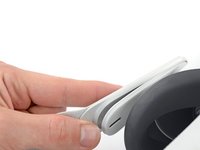
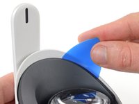
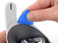
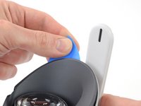
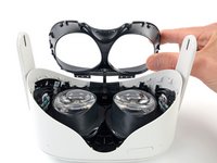
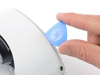
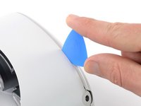
Lift the eyepiece trim slightly and tilt it towards the top edge of the headset.
-
Set the trim down on your work surface, making sure not to strain the cable.
-
-
-
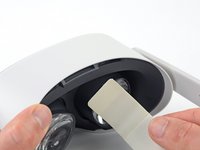
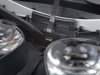
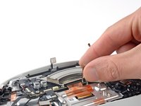
Use the point of a spudger to flip open the black lock tab on the ZIF connector securing the face sensor cable.
-
-
-
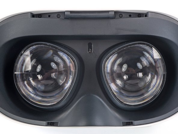
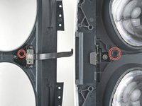
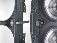
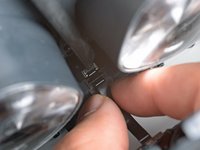
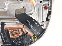
Make sure the lens spacing matches the spacing indicator. This allows the indicator peg to sit correctly in its notch.
-
If the lens spacing doesn't match the indicator, manually adjust the lens with your fingers.
-
-
-
Thread your fingers through the eyepiece trim’s eyeholes and grasp the edges of the sensor cable.
-
Slide the sensor cable into the socket until the first set of tabs rests in the socket. This should flip the lock tab down partially.
-
Use a spudger to press the lock tab down towards the cable to lock it in place.
-
-
-
Use a Phillips screwdriver to remove the five 7.7 mm‑long screws securing the front cover to the headset:
-
One recessed in the top-left corner
-
One recessed in the top-right corner
-
Three along the lower edge
-
-
-
Insert an opening pick into the seam between the bottom edge of the front cover and the headset.
-
Pry with the opening pick to release the front cover clips.
-
-
-
Outil utilisé dans cette étape :Tweezers$4.99
-
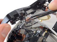
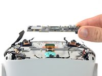
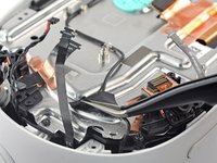
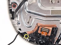
Use a pair of tweezers to grasp the metal neck of the top-right antenna cable.
-
Lift the antenna connector straight up to disconnect it.
-
Guide the antenna cable out of its metal clip holding it in place.
-
-
-
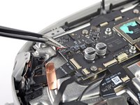
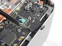
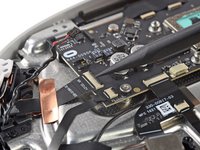
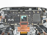
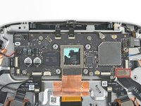
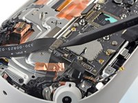
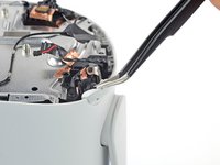
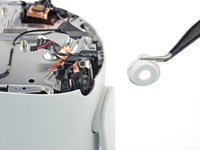
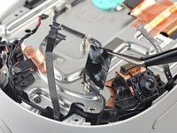
Use a Phillips screwdriver to remove the three screws securing the battery cable bracket:
-
One 4.4 mm‑long screw
-
Two 2.3 mm‑long screws
-
-
-
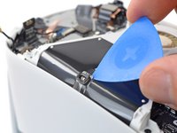
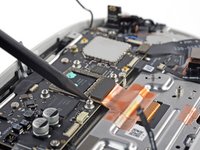
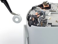
Use a spudger to pry up and disconnect the battery press connector from the motherboard.
-
-
Outil utilisé dans cette étape :Tweezers$4.99
-
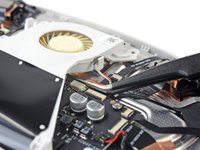
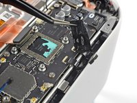
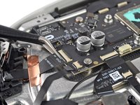
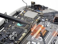
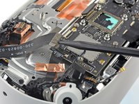
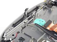
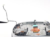
Insert one arm of a pair of tweezers under the metal neck of the black antenna cable near the fan assembly.
-
Lift the antenna connector straight up to disconnect it.
-
Guide the antenna cable out of its metal clip holding it in place.
-
-
-
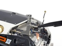
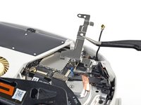
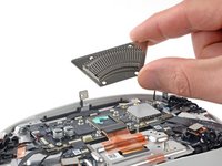
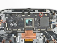
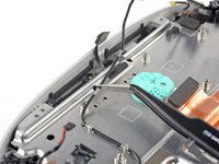
Use a Phillips screwdriver to remove the eight screws securing the antenna assembly to the headset:
-
Four 4.4 mm‑long screws
-
Two 4.8 mm‑long screws
-
Two 10.7 mm‑long screws
-
-
Outil utilisé dans cette étape :Tweezers$4.99
-
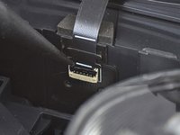
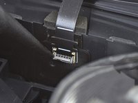
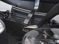
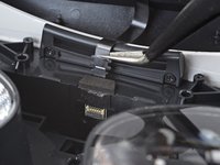
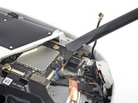
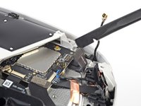
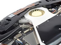
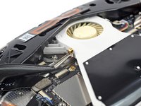
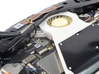
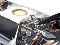
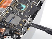
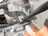
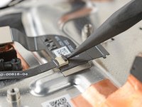
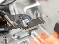
Use tweezers to grab the fan connector and carefully slide it out of its socket.
-
-
-
Use the point of an opening pick to loosen the adhesive securing the LED flex cable from the top of the fan assembly.
-
-
-
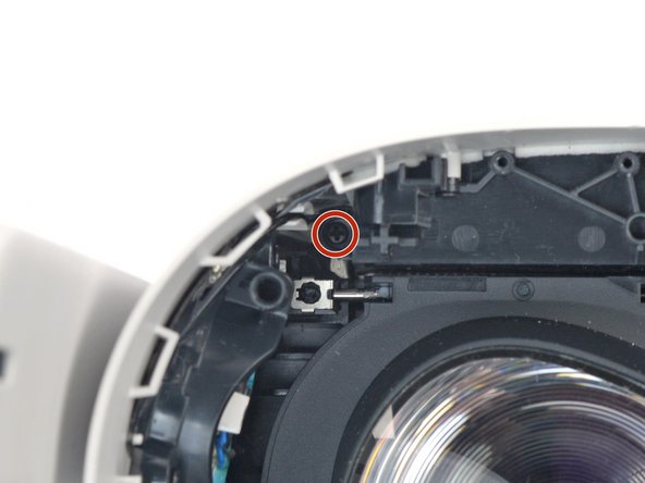
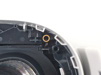
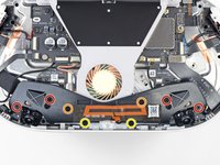
Remove the two screws securing the fan assembly to the headset:
-
One 4.4 mm‑long Phillips screw
-
One 3.6 mm‑long Torx T2 screw
-
-
-
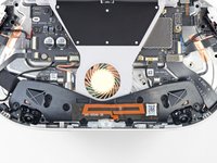
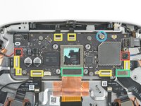
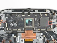
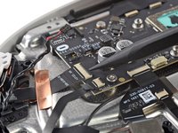
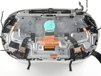
Use a Phillips screwdriver to remove the four 2.3 mm‑long screws securing the heat sink to the motherboard.
-
-
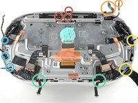
-
Two speaker connectors
-
Seven ZIF connectors
-
Two press connectors
-
One antenna connector
-
-
Outil utilisé dans cette étape :Tweezers$4.99
-
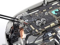
Use tweezers to grip the left speaker cables at the base of their motherboard connector.
-
Lift the connector gently straight up to disconnect it.
-
-
-
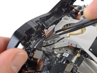
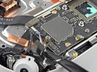
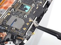
Use tweezers to gently peel the black tape covering the two top flex cables.
-
-
-
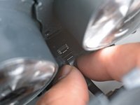
Use a spudger to pry up and disconnect the display cable.
-
-
-
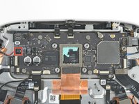
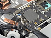
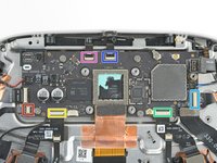
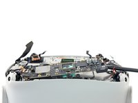
Remove the five screws securing the motherboard to the headset:
-
Four 3.8 mm‑long Phillips screws
-
One 6 mm‑long 3.5 mm hex standoff screw
-
-
Outil utilisé dans cette étape :Tweezers$4.99
-
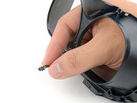
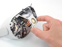
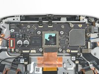
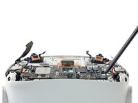
Use your fingers or tweezers to peel and remove the two camera covers from the top cameras.
-
-
-
Peel and remove the black tape covering the antenna cable.
-
-
-
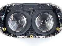
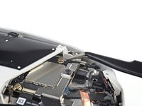
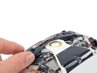
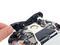
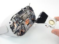
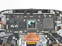
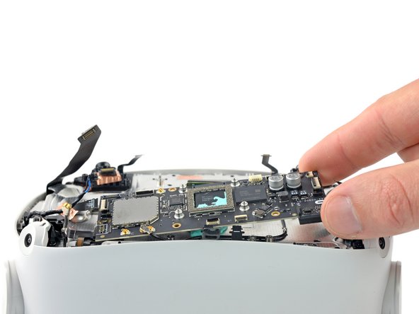
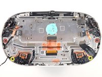
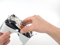
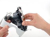
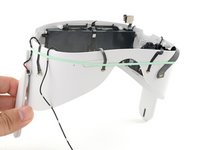
Grasp the screen and lens assembly with your fingers.
-
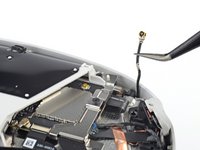
Slowly lift and separate the assembly from the outer shell, taking care to reposition any cables that get in the way.
-
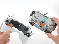
Remove the screen and lens assembly.
-
-
-
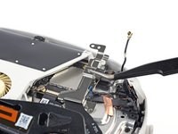
Three cables along the top edge—two flex cables and one LED flex cable
-
Two cables in the top right corner—the battery connector and an antenna cable
-
Two cables along the right edge—an antenna cable and a wide flex cable
-
Two flex cables along the bottom edge
-
Three cables along the left edge—one antenna cable, one flex cable, and one speaker cable
-


To reassemble your device, follow these instructions in reverse order.
Take your e-waste to an R2 or e-Stewards certified recycler.
Repair didn’t go as planned? Try some basic troubleshooting, or ask our Answers community for help.
To reassemble your device, follow these instructions in reverse order.
Take your e-waste to an R2 or e-Stewards certified recycler.
Repair didn’t go as planned? Try some basic troubleshooting, or ask our Answers community for help.
Annulation : je n'ai pas terminé ce tutoriel.
5 autres ont terminé cette réparation.


5 commentaires
I had mine outside for less then a minute and i had a long yellow line Across the screen and i know it would be cheaper to fix it yourself and you having a step by step instructions on how to fix it is the absolute best thing i have seen a console developer do so you doing this probably super helpful to so many people Thank you
If it doesn’t bother you too much, wait until you need to fix something else(i. e. the battery) and replace the screen with it. If it is a big line, then consider replacing it.
Hello, i need to replace my lcd 'cause sun burned it, whats the name of the "glue" that holds the lcd to his frame?
I followed every step, but now my controllers won't connect and they keep buzzing. the quest doesn't track my movements neither. I performed a factory reset, and now I only have sound. I only see an image when I try to turn it off, but the images sticks in front of me the pointer doesn't move. I double-checked all internal connections, and everything appears to be correctly connected. Does someone know the problem? Thanks!