Cette version peut contenir des modifications incorrectes. Passez au dernier aperçu vérifié.
Ce dont vous avez besoin
-
-
Insérez un outil ou embout éjecteur de carte SIM ou bien un trombone déplié dans le petit trou situé sous le tiroir de la carte SIM, près des caméras arrière, le long du bord du téléphone.
-
Appuyez fermement pour éjecter le tiroir.
-
-
-
Retirez les deux vis T2 de 2,6 mm de part et d'autre du port USB-C, sur le bord inférieur du téléphone.
What are the reference of the screws ? They are missing in the one I bought !
Hi Yôken,
They help hold the back cover on. Most of the time, the clips are enough to hold the phone together.
Just FYI, for whatever reason my brand new OnePlus 5 had 0,8 mm stars screws instead of T2 Torx.
Definitely T2 for me. Do watch out during assembly. I have a feeling that it’s easy to strip these.
T2 for me too. It was missing in my kit and iFixit sent it later when I asked them about it.
-
-
-
Jointure de l’écran : celle-ci fait partie de l’écran. Ne faites pas levier ici ou vous allez dissocier et endommager l’écran.
-
Jointure du châssis : c’est là où le châssis en plastique touche la coque arrière. Il est encastré dans la coque arrière. Faites levier uniquement ici.
-
Il y a douze clips qui maintiennent le châssis contre la coque arrière. Soyez attentif à leur emplacement lorsque vous ferez levier pour retirer la coque arrière au cours des étapes suivantes.
-
-
-
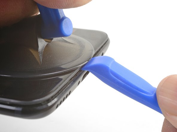
Placez une ventouse près du bord inférieur de l’écran.
-
Tirez fermement sur la ventouse avec une force constante.
-
Insérez l’arête d’un outil pour ouvrir directement dans la jointure du châssis, près de la ventouse, jusqu’à ce qu’il se glisse entre le châssis en plastique et la coque arrière.
I found the suction cup to be more of a hindrance and kept hitting the power button, making it necessary to stop and turn the phone off again. I watched a youtube video where the person didn't use a suction cup at all and decided to try that. I also found that a guitar pick type spudger worked far better than the one shown in the picture. If you're having trouble getting it started, I suggest trying those two things.
-
-
-
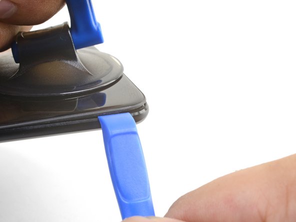
Une fois que l’outil pour ouvrir est en position, faites-le glisser le long du bord inférieur du téléphone.
-
Manœuvrez avec précaution l’outil autour du coin gauche du téléphone, afin qu’il reste dans la jointure.
This was extremely difficult & took a lot of force. I needed a thin flat metal spudger and wrecked a couple of plastic ones in the process. I left a few scratches along the join in the process. It would be easier if I had something to hold the phone, in my hand I kept turning it on by accident.
what was the metal spudger did you use? I am having trouble as well. I cannot seem to pry the back cover and it feels like it is shut tightly, there are no crevices I can pry into. What was your strategy may I ask?
At first, I slightly opened the body with a plastic tool, but it was not enough to actually open the back cover. Then I used a thin metal screwdriver for this. It was difficult but nothing special. Just be sure that you are opening the correct seam between the body and the screen and don’t make sudden moves. I bent nothing, everything came back in place when reassembled.
ivan -
Same as David here: the plastic opening tools/guitar picks were doing nothing (not even creating the first "crack") . In the end I managed to open it using Jimmy (the metal knife/spudger), but not without scratching the whole metal cover.
-
-
-
Continuez à faire glisser l’outil le long du bord long, en détachant les clips au passage.
-
-
-
Une fois que les bords inférieur et gauche du téléphone sont détachés, remuez légèrement le châssis pour détacher les clips supérieurs et droits.
-
Alignez l’arête supérieure du châssis avec la coque arrière et assurez-vous que les clips supérieurs sont en place.
-
Appuyez sur le long des long bords du téléphone pour attacher les clips restants.
Reinstalling the back cover stumped me for a second… If you’re struggling with aligning the top edge of the frame, remember that the camera is going to look off/pointed a bit too low until you actually clip the frame back in.
Really stupid but it was the only thing that tripped me up in this guide.
-
-
-
-
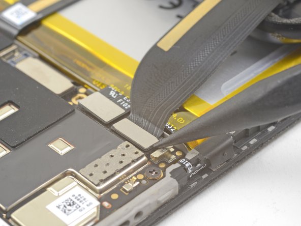
Utilisez la pointe d’une spatule pour faire levier et débrancher la nappe d’interconnexion de la coque arrière de sa prise.
If the flex cable pins are damaged, the flex cable can be replaced.
If the connecter pins (on the motherboard) are damaged, you might need to do microsoldering (or contact a microsoldering company) to replace the damaged connector.
Brendan -
-
-
-
Utilisez la pointe d’une spatule pour faire levier et débrancher le connecteur de la batterie de sa prise.
-
-
-
Retirez les six vis cruciformes de 2,6 mm qui maintiennent le haut-parleur au châssis.
-
-
-
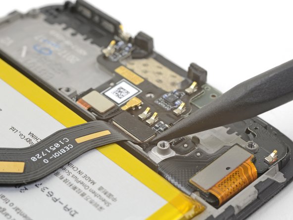
Utilisez la pointe d’une spatule pour faire levier et débrancher la nappe d’interconnexion de sa prise.
This step is used in multiple guides, and not all of them require the cable to be bent away. You can just leave it sitting there, disconnected.
This image seems to show the daughterboard removed but there is no corresponding previous step. I see no way to remove the interconnect flex cable without removing the daughterboard. Possibly the volume switch can be removed with the cable still connected but I'm not confident enough to try this so will remove the daughterboard.
David,
Thanks for bringing this up. That's indeed a procedural error! I've added the missing steps in the affected guides.
-
-
Cette étape n’est pas traduite. Aidez à la traduire
-
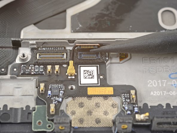
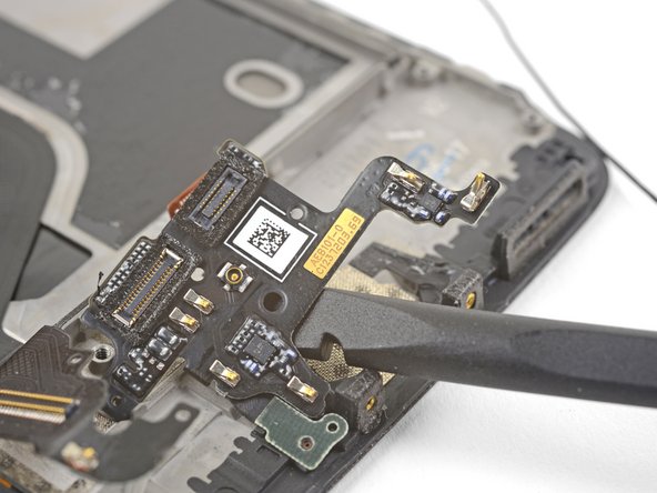
Use the point of a spudger the pry up and disconnect the fingerprint scanner connector from its socket on the daughterboard.
-
-
Cette étape n’est pas traduite. Aidez à la traduire
-
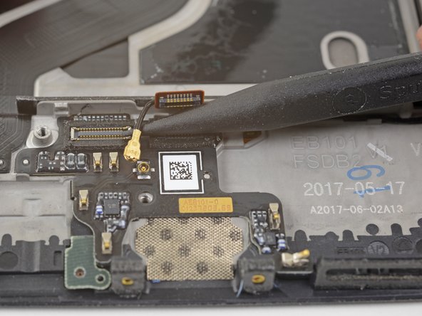
Slip the point of a spudger underneath the antenna interconnect cable and pry up to disconnect it from its socket on the daughterboard.
-
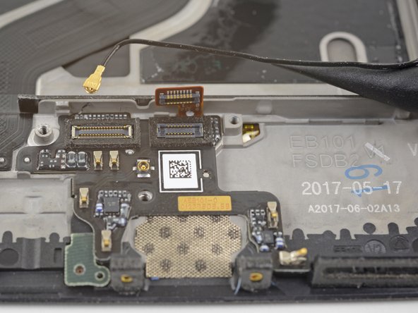
De-route the antenna interconnect cable out of the way of the daughterboard.
-
-
Cette étape n’est pas traduite. Aidez à la traduire
-
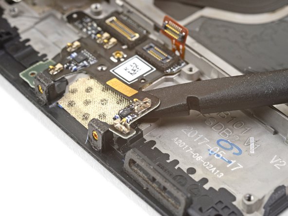
Insert the edge of a flat end of the spudger underneath the microphone board and twist slightly to release the board's adhesive.
-
-
Cette étape n’est pas traduite. Aidez à la traduire
-
Slide the flat end of a spudger or the point of an opening pick underneath the daughterboard near its right edge.
-
Gently pry to loosen the daughterboard from its recess.
-
-
Cette étape n’est pas traduite. Aidez à la traduire
-
Insert the flat end of a spudger underneath the daughterboard, this time approaching it from the bottom.
-
Twist and slide the spudger slightly to release the daughterboard from its recess.
-
-
Cette étape n’est pas traduite. Aidez à la traduire
-
Slide the flat end of a spudger underneath the tape covering the fingerprint scanner.
-
Lift up to pry and remove the tape.
Hello! Does this silicone tape have the same thickness as the mesh that will be removed during disassembly? Do you have a mesh like that available or do you know a place to purchase it online?? Thanks
-
-
Cette étape n’est pas traduite. Aidez à la traduire
-
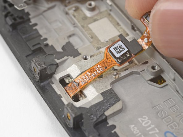
Use your finger to gently lift up the connector end of the fingerprint scanner. Pull upwards slowly. Do not pull directly away from the fingerprint scanner.
-
Keep pulling upwards until the fingerprint scanner cable is freed from its recess.
I couldn’t release this by pulling upwards as shown. Maybe I wasn’t brave enough & could have pulled harder. I used a fine pointed end of a scalpel blade under the left side where the QR code is & that, while pulling gently, did the trick.
-
-
Cette étape n’est pas traduite. Aidez à la traduire
-
Insert the point of a spudger into the marked areas on either side of the flex cable, and push until the fingerprint scanner is loosened from its recess.
-
-
Cette étape n’est pas traduite. Aidez à la traduire
-
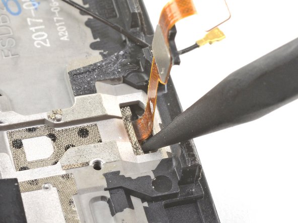
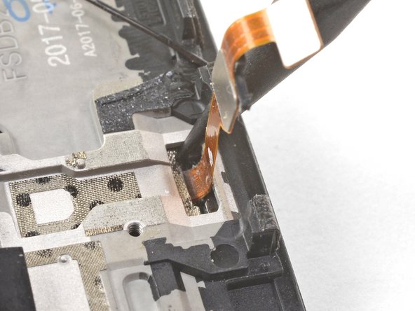
Once the fingerprint scanner is loosened from its recess, carefully thread its flex cable through the cutout, out of the front of the display.
-
Remove the fingerprint scanner.
My replacement fingerprint scanner did not come with any adhesive to hold it in place and it floated above the surface of the phone. I used a tiny amount of very carefully applied Gorilla contact adhesive which worked but will be a pain to remove next time.
-


Annulation : je n'ai pas terminé ce tutoriel.
Une autre personne a terminé cette réparation.


8 commentaires
Is there an extra step involved so that the button stays countersunk in the new display? Mine seems to be slightly proud of the screen
Hi John,
If you may need to apply some new adhesive to the underside of the fingerprint sensor to hold it in place.
Hi,
I change the fingerprint but only works if don’t close the back cover, when I close the back cover the OS don’t detect the fingerprint sensor. Any idea?
Hey César,
It may be that something is shorting the fingerprint sensor. Did you replace the tape in step 24 with electrical tape?
Great news, finally I found the problem, the connector from daughter board to motherboard was disconnected but a lot of pins maked contact and the micro, and other electronics works but not the fingerprint sensor. I dissasembled the motherboard and pushed the connector from the flex cable to the socket, now all is working ok. Thanks for the response Arthur!
I’m glad you fixed the problem! Thanks for following up!
Hello everyone ! I’m trying to fix my oneplus 5 too. I’m currently replacing the home button but it does not stay in place (the button just ‘stick out’ from the screen). @arthurshi Does the home button must have an ‘adhesive band’ to stick to the screen ? It does not seems to be a clip-able button. I’m not talking about this side https://d3nevzfk7ii3be.cloudfront.net/ig... . I’m talking about the other, the black ‘screen’ side.
Thank you for your work.
Hi Michaël!
Good question! The button does have some adhesive on it. If the existing adhesive no longer holds the button, I suggest using some double-sided tape to hold the button in place. If you are certain your repair fully works, you can also glue the button down with a bit of E6000 adhesive.