Introduction
Use this guide to replace your Retina MacBook's lower case assembly together with the battery as a single unit. Follow this guide if you’d like to separate the battery from the case.
To avoid logic board damage, when your MacBook repair is complete but before powering it on, connect it to low-voltage power using a 5-Watt iPhone charger and a USB-C to USB-A cable. These accessories are not included with your MacBook, so make sure you have them ready before you begin.
Ce dont vous avez besoin
-
-
Remove the following eight screws securing the lower case:
-
Two 1.8 mm P5 Pentalobe screws
-
Four 2.9 mm P5 Pentalobe screws
-
Two 6.1 mm P5 Pentalobe screws
-
-
-
Lift the upper case and display together from the front edge and raise it to about a 45˚ angle.
-
-
-
Use the flat end of a spudger to press and hold the small gold 'battery disconnect' button.
-
If the power LED is lit up, continue holding the button until the LED goes dark, and then release. This may take up to 10 seconds.
-
If the LED does not light, release the button after 5-10 seconds. Press and hold it again for 5-10 seconds, and release. Finally, press and hold it a third time for 5-10 seconds, and release.
Wow okay could someone explain why this is necessary? What happens if you skip this step and simply undo the screw to disconnect the power?
Removing the screw does not disconnect the power—power comes from the battery terminals contacting the underside of the logic board, and they’re tricky to separate reliably at this stage of disassembly. This step is the safest and easiest way to kill power; don’t skip it.
Hi what will happen if i skip this step, coz i did tried to power down the battery by pressing small gold button, but no avail. the LED light still there even after more than 5 times press (5-10secs or more) each press.
Did you learn the answer to your question? I'm having the same issue -- I keep pressing the gold button but the battery light stays on.
R McP -
Mi laptop doesn’t turn it on doing that ):
-
-
-
Lifting from the front edge, open the lower case to an angle of about 45°.
Before the IPD flex cable can be removed the battery disconnect button has be held down for up to 10 seconds. If the LED near the battery connector is switched on it shows that there is power going through the logic board from the battery, once the button is pressed and this light goes off the machine is safe to be worked on.
-
-
-
Use tweezers to peel back the tape covering the trackpad cable ZIF connector.
Only peel back the first half of the tape covering the trackpad cable ZIF connector—do not completely remove.
Gently - lift tape while wiggling cable side to side. Be sure tape is released, but do not remove completely
-
-
-
Use a spudger to carefully flip up the retaining flap on the trackpad cable ZIF connector.
This is very tricky indeed - at least on my computer. I failed at this point - having skipped to it as sugested above so as not to stress the ribbons on the other side. The ZIF was not as I expected. They had opened when I pulled up the stick cover and I found I was working on the socket itself. The top edge came adrift after almost no pressure being put on it. The ribon did not come free with gentle pulling though. At that point I put the back on again… waited until the battery recharged a bit and found I had not nroken it after all. I doubt I shall try again. It is much harder to replace than the 15 inch - much…
I’ve just found that I have broken it after all. No keyboard. Bluetooth still works so I can use the machine.
All in all, an expensive mistake. BTW - I did NOT get the kit from IFIXIT - not sold here.
I found “Recognizing & Disconnecting Cable Connectors”
Reconnaître et débrancher les connecteurs
useful, esp. for someone who has not used ZIF connectors and retaining flaps before. There are several retaining flaps that need to be opened. The first time is tricky as you need a sense of how much force to apply. I used the flat end of the provided spudger. Apply progressively firmer upward pressure until the retaining flap pops open. The first time is tricky, but straightforward thereafter.
Mouse back and forth between the two right-side thumbnail photos and you will get a little animation feel showing how these ZIF connectors operate—it's very helpful. Apply light but consistent pressure to pop them up. Helps to go side to side if they're a little stubborn.
-
-
-
Disconnect the trackpad ribbon cable from the trackpad by pulling it gently through its slot in the frame.
it would be nice to have a specific picture of the cable and contacts and how it is oriented in the ZIF connector. This isn't clear in any of these photos or text.
My trackpad cable snapped so had to replace it and none of the replacement cables have the tape which is on the smaller end to the trackpad. The other end is fairly easy to figure out but the trackpad end isn't as the cable makes a 180 degree turn inside the case (poor design).
-
-
-
Carefully turn the MacBook over, so that the lower case lays flat.
-
Raise the upper case/display assembly to about a 90° angle, and prop it up against something sturdy so you don't have to hold it.
-
Add a piece of tape near the track pad to secure the upper case and prevent accidental movement.
You can open the laptop screen all the way open with it flat in the table (screen facing up) and the keyboard should stay up.
-
-
-
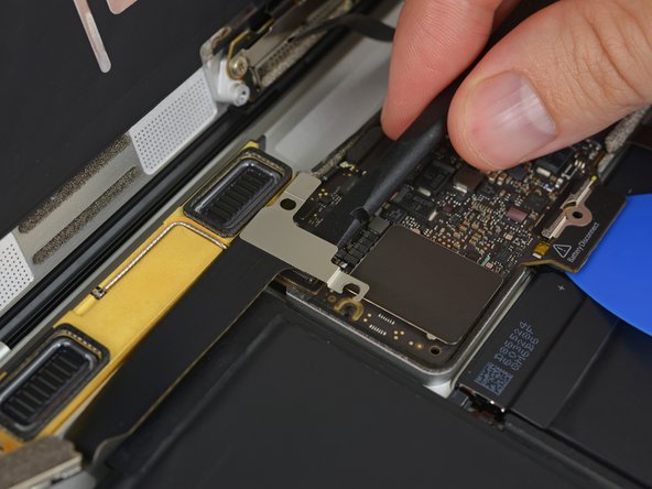
Remove the single 2.9 mm T5 Torx screw securing the battery connector to the logic board.
the moment you opening macbook case and before any tinkering with connections, you MUST press little yellow button on logicboard, located on the right from battery connector - this will disable all power to the board. You can check by looking at the small led on left side of the battery connector - if there is very faint light, it means that power is still there. After pressing button light should go off. Removing screw is not necessary at all, and like I said - you MUST disable power before any touching to connections etc.
Where it says
“2015 models have a silver grounding clip with two foam pads directly under this screw“
I have a 2015 MacBook & the grounding clip is not there!
I’m using this guide to investigate why there are lines on screen or darker screen at certain angles of opening it. Also a background ghosting effect on screen too.
No obvious damage or loose connectors so wondered if the lack of grounding clip can cause these symptoms?
Anybody out there know?
Either buy the clip and check, or replace the screen (or LB), but the macbook would more likely not start if there is a missing grounded connection, depending on what is being grounded.
Sean -
-
-
-
As an added precaution, you may physically disconnect the battery by inserting a battery isolation pick between the logic board and the battery connector.
I HAD TO DO THIS TWICE. After replacing the battery while following this guide to a 'T', the battery was not being recognized by the logic board. Strangely, with the power unplugged it would still light up the screen and tell me the battery was at a critical level, but it would not boot. Resetting the SMC had no effect. I thought I killed my computer or got a bad battery, so as a last ditch effort I re-opened the case, pressed the battery disconnect button, removed the screw and inserted the battery separation tool again to Physically Disconnect the battery from the mainboard. After about 5 minutes I then removed the tool and reassembled everything, plugged in via 5v iphone charger and USBA-C cable again and LO, the battery is now reporting correctly, charging correctly and allowing me to boot on its power .
-
-
-
Remove the two screws securing the USB-C port cable bracket:
-
1.1 mm Tri-point Y00 screw
-
3.5 mm T5 Torx screw
I should have read the comments before using the provided 1.1 mm Tri-point Y00 bit. I almost stripped the screw but was able to use a small flat head bit to open the screw.
Ifixit: you may want to update this part in the instructions. Not everyone reads the comment section, esp. when it comes to specification of bits which is basic and must be accurate. This is one of the more critical ones in the procedure that can easily go south. The rest of the instructions are excellent.
early 2015 model here. I’ve used a Y1.5 with cautiously applied down force.
My 2015 had a 2.5mm Y screw not a Y000.
Adding to the helpful comments above, on replacing the 1.1mm tripoint screw, I found the the magnetism of the nearby speaker coil overcame that of the driver and would draw the screw away or the combo of forces would fling it out of the work area! After fiddling with it for too long, I used some of the battery adhesive removed earlier to attached the screw to the driver. Wax would probably work better if I’d had some.
I used the PH00 head to unscrew what they call the “1.1 mm Tri-point Y00 screw”, NOT the Y00 head, and it unscrewed perfectly fine.
Agreed, my screw was a PH00.
I have an early 2015 MacBook and it was a PH00 head I needed to use.
-
-
-
Use the flat end of a spudger to disconnect the USB-C port cable bracket by prying it straight up from the logic board.
Emphasis on aligning the bracket correctly. What the pictures do not show is that underneath the flat part of the metal bracket (the area between the two screw holes) is a connector that needs to be accurately aligned. Aligning the two screw holes does not imply that the connector is seated correctly.
After I re-assembled my 2015 MacBook power would not come on. I thought I had damaged the logic board despite being careful and following instructions. Diagnosing the problem took a while. Retracing the steps and focusing on power supply I was able to determine that the metal flap which hides the connector underneath had not made proper contact.
What I did was to use a finger to get a tactile feel for the connector underneath the metal bracket aligning properly and then press down vertically when it seemed to be aligned. It’s a subtle tactile feel. After re-doing this step, I got power back. Be careful not to damage the connector as noted in the instructions.
Good tip. It’s so easy to damage these fragile connectors by forcing the plug in and reattaching the mounting plate screws
-
-
-
-
Disconnect the audio jack board ribbon cable by pulling it straight back out of the ZIF connector.
The audio jack cable is a bit of a pain to reinsert. I found if I turned the screen and the bottom on its side, like an open book, I had much better orientation and it was much easier to insert.
Excellent guide and all works like a sharm, but was one issue. After full assemble there wasn't sound. Then I open Macbook again and disconnect and connect audio cable. You must insert cable so, that white stripe will not visible. And sound reveal!
This helped me, thanks!
-
-
-
Use tweezers to peel back the tape covering the display cable connector.
-
-
-
If so, use the flat end of a spudger to hold down the retaining flap while peeling the tape away with the tweezers.
-
-
-
Disconnect the display cable by gently pulling it straight out of its connector.
A step was skipped. You have to flip up the metal locking tab on the socket before the cable can be removed. See the photo.
And be careful when re-inserting the connector. One end of the two indentations got a little bent (I did not notice) which resulted in a black screen when powering up. I used a heat gun (low setting) to separate the cable from the labtop housing. When re-assembling, first insert the connector (after closing the metal flap as instructed), verify that it’s properly seated, then re-attach the rest of the cable to the laptop housing. In the first try, I first re-attached the cable to the housing, then tried to insert the cable connected into the metal socket. Because of a lack of slack, the cable connector at one end got bent slightly. After identifying the problem, I had to straighten it/unbend out using my fingers. Hence it is easier to insert the connector first, then attach the rest of the cable to the laptop housing.
Black screen upon reboot:
Inserting the display ribbon cable into it’s contact without closing the metal flap before reassembly will result in a black screen.
I live in a colder climate (and it's winter now) - a hair dryer was absolutely necessary to get this cable loose.
The flap must remain closed when the cable is reinserted during reassembly. Carefully line up the cable with the gold contacts facing down, and gently slide it into the connector.
OK, when I read those directions, I did it wrong. I followed the instructions and kept the flap closed when the cable was reinserted during reassembly. Of course I got a blank screen. It should read the flap must be closed AFTER the cable is reinserted during reassembly.
-
-
-
Use tweezers to peel up the tape covering the two ZIF connectors—one for the right speaker cable, and one for the audio jack board cable.
Removing the logicboard must be safer way, but battery replacement can be accomplished if you skip here to step 32, and omit 36.
I'm not sure removing the logic board is safer, you have many more opportunities to break something. I left it connected but removed the screws so I could maneuver the battery underneath. Faster and safer imo.
I would strongly advise anyone tempted to follow this advice and skip to 36 to NOT DO THAT. The hardest part of this whole project is removing the old batteries and adhesive. You’re going to want to use the adhesive remover liberally. Getting that on your board, or accidentally gashing at it when you’re trying to wedge out the old battery, is going to ruin it. Trust me, you would hate to go through all this just to find out you fried your board because of this (admittedly tempting) comment. There are seemingly a lot of steps from here to 36, but they’re all pretty easy and fast. KEEP GOING! KEEP FOLLOWING THE INSTRUCTIONS. YOU WILL MAKE IT!
RDG -
-
-
-
Insert one arm of your angled tweezers under the metal neck of the first antenna connector and pry up to disconnect it.
The supplied tweezer is no good. You need one with grooves as shown in the picture. When re-inserting the antenna connectors, make sure that they are seated properly before pushing down. If you have magnifying equipment, use that to get visual confirmation. I used tactile feedback from my fingers to discern proper alignment. Try not to force it.
I used the tweezers provided by iFixit. I struggled with both connectors and finally managed to disconnect both, but when I came back to reconnect them, I realized that both connectors on the logic board were loose. Long story short, it turns out that my little exciting adventure changing the battery cost me $530 to send it for repair at Apple Care. I am quite good at troubleshooting Mac and used to work for Apple for many years. This one step is more dangerous than it seems, because you can end up like me, without wifi on your mac. Honestly, for those who think they can do it, think twice. You can thank me later…
For me this step was the only point where I had a bit of trouble. The supplied tweezers were not the best for disconnecting the antenna connectors as Ki Park points out already. In my case the outer ring of one of the connectors on the logic board bended slightly. It bended back in place during assembly and the wifi works as normal again after the repair. It is very tricky though, really be careful in this step and use other tools as necessary.
BY FAR THE MOST DANGEROUS PART OF THE JOB!. I broked one connector and spent an hour with high powered magnifiers to try a repair. Wasted an hour on this. Id suggest leaving the logic board in place if possible
F. I broke one
I actually put one of the tweezer tines under the connector and used it as a lever gently to pop the antenna connector off the housing. Worked well, but I had to be super careful not to break anything.
These connectors are incredibly finicky to reinstall. Precise alignment is critical. You can sort of get a sense of when the connectors are properly aligned by trying to slide them side to side with your finger, but mostly it's a case of trial and error. Don't apply excessive force because you risk damaging the edges of the connectors. When properly aligned they don't exactly click, but you do feel them go in.
DO NOT REMOVE THESE. As others have stated these are fragile and finicky to remove and reinstall. Instead, leave them intact and lift up the logic board at a 70 to 80% angle. Use a piece of tape secured to the bottom edge of the computer and the top edge of the logic board to hold it up and out of the way. If you are diligent, you can remove the batteries without touching or messing with the logic board. Use caution, don't get too overzealous, take your time.
tough one - you guys scared me... SOLUTION: HOLD A SECOND TWEEZERS WITH STRAIGHTEDGE ON THE INSIDE EDGE WHILE GENTLY USING PROVIDED POINTY TWEEZER ON THE OPPOSITE SIDE TO PRY UP THE CONNECTOR. FLAT TWEEZER PROVIDES JUST A HINT OF BACK PRESSURE, KEEPS THINGS STRAIGHT WHILE YOU INSERT THE POINTED TIP AND PRY UP GENTLY. INSERT AND LEVER IT UP - I.E. AFTER INSERTION, TWIST THE POINTED END SO PRESSURE IS STRAIGHT UP, FROM UNDER THE MIDDLE OF THE CONNECTOR - DON'T INSERT AND PUSH AWAY FROM YOU. MINE POPPED RIGHT UP THIS WAY (after exploring all other options). IMPORTANT - THE POINTED TIP (PRY SIDE) COMES FROM OUTSIDE OF CASE , OPPOSITE SHOWN IN PICTURE (AS MENTIONED BY PRIOR COMMENTER.). I ACTUALLY NEED RELATIVELY LITTLE PRESSURE USING THIS METHOD TO GET THE CONNECTORS TO POP. INSERT POINTY TIP UNDER THE NARROW SPOT JUST AHEAD OF THE WIRE, BUT BEFORE THE SOCKET
-
-
-
Pry up the second antenna connector to disconnect it.
Broke a connector. Now what?
BEWARE - there are no instructions on how to reassemble this. It goes to step 52 - battery installed and that is it. Easy to pull out, almost impossible to put back in afterwards. So STUDY this to get an idea of how to reattach.
-
-
-
Use a spudger to disconnect the left speaker cable connector by prying it straight up from the logic board.
Reassembling NOTE. The left speaker cable needs to be below the logic board when screwing in the right screw. Otherwise you will have to backtrack.
-
-
-
Disconnect the trackpad cable from the logic board by gently pulling it straight out of its connector.
Once the logic board has been replaced, when following these instructions in the reverse order it should be pointed out that the all the flaps are flipped down. A distracted person might try to force in the flat connector before realising that he has to flip up the flap of the new logic board.
Ok, went decent but on reconnecting the trackpad cable which I had to replace, it isn't clear which side goes up and which side goes down. From the photos, it appears the copper coated side is down at least on the logic board. Is this the same on the trackpad connector?
I can't quite find a clear photo of the copper surface position on either end of the ZIF trackpad insertion.
HELP!
-
-
-
Flip up the front edge of the logic board.
-
Lift and detach the EMI tape securing the logic board to the lower case.
“Reattach the tape securely during reassembly.”
In my case the tape did not stick properly to the lower case anymore and also came a bit loose from the logic board. Nonetheless my macbook works fine after the repair, so I'm not sure how important the EMI tape is. If I experience problems in the future I might open the macbook up again and check the tape and perhaps reattach it better with some new glue. There is probably special glue needed, so I'll look into that when it becomes an issue.
-
-
-
Remove the logic board.
If you are replacing the logic board once the machine has been rebuild the 2015 model has to have a 5W power adapter plugged into the machine first before the full 29W power supply otherwise there is a risk of damaging the logic board. Once the power is supplied the battery disconnect LED will switch on and once this has occurred you can remove the 5W and supply the machine with the full 29W power adapter.
While it’s true that the internal documentation specifies this for a 2015, after frying 2 motherboards with a normal charger, I spoke with the engineers and they told me that this also applies to 2016 and 2017 macbook main logic boards. I say- It can’t hurt to try to wake them up with a 5 watt charger first! Please take 5 minutes to save your motherboard.
Noah -
-
-
-
Using tweezers, remove the foam pad covering the screw on the left side of the right speaker.
-
-
-
Prepare an iOpener and heat the lower case directly beneath the right speaker for 1-2 minutes, in order to soften up the adhesive securing the speaker.
-
-
-
Using tweezers, remove the foam pad covering the screw on the right side of the left speaker.
-
-
-
Prepare an iOpener and heat the lower case directly beneath the left speaker, in order to soften up the adhesive securing the speaker.
-
-
-
Carefully peel away the audio board ribbon cable from the adhesive securing it to the lower case.
-
Remove the audio board ribbon cable.
-


To reassemble your device, follow these instructions in reverse order. To avoid logic board damage, when your MacBook repair is complete but before powering it on, connect it to low-voltage power using a 5-Watt iPhone charger and a USB-C to USB-A cable.
To reassemble your device, follow these instructions in reverse order. To avoid logic board damage, when your MacBook repair is complete but before powering it on, connect it to low-voltage power using a 5-Watt iPhone charger and a USB-C to USB-A cable.
Annulation : je n'ai pas terminé ce tutoriel.
10 autres ont terminé cette réparation.

3 commentaires
Nice guide and though indeed not easy, not difficult if you're careful... note I invested in the set of iFixit tools and having those really is a good investment... given they saved me a Macbook that the repair shop said would cost 2000Eur to repair (and would give me 200Eur as a scrap price)... found the bottom case/battery set on eBay for 150... did the guide, and back in business :)
Does anyone know the correct orientation of that touchpad cable?
If, like me, you didn’t have a P5 Pentalope screwdriver but did have one that fits an iPhone.
You can sand down the tip until it’s the right size.
Stuart - Réponse
Thank you Stuart! I would never have thought of this and it worked perfectly.
R McP -
Hello,
where do I plug the USB-C to USB-A cable on MacBook MacBook Pro (Retina, 15-inch, Mid 2015)
I can’t any port suitable for USB-c !??
sissi - Réponse
My MacBook had P4 pentalobe screws, notP5
Greg Lavardera - Réponse
Big thanks to Jeff for such thorough and detailed instructions. This is definitely a more advanced repair so if you're not comfortable with making such repairs, like having experience working on iPhones, computers, etc., you might think twice before attempting. It's very helpful to read all the instructions thoroughly before starting. Plan on 3 to 4 hours—the battery removal along with its adhesive is a real $@$*-show, but totally doable if you followed Jeff's recommendations.
I'll post a few tips in the comments on each step that I think is worth noting but I will mention here one of the trickier steps. ZIF connectors on the flat cables can be a little tricky, especially if you have never done these. Before attempting to do the first one (step 8) review the others in steps 16, 20, and 25. You'll get a better sense of how these little retaining flaps flip up and what they actually look like when you study each photo in each step—they are very tiny and fragile.
Steven Gibson - Réponse
Just finished replacing the battery. I followed the directions that came with the battery instead of this guide. In short, Steps 15 to 35 are not necessary. You don't have to completely disassemble the laptop to replace the battery.
Andrew Mohan - Réponse
Thanks. I skipped it too and it worked.. It was a painstaking to remove the two side batteries as the cables were connected. But a little patience gets the job done. I did however remove the audio jack connector but from the audio board. Removed the display connector and the usb-c bracket to get the bottom case free.
Paras Tolani -
READ EVERY STEP, AND EVERY COMMENT FOR THAT STEP BEFORE ATTEMPTING! Go slow. Think first. Be organized. No probs.
David Nagle - Réponse