Introduction
Follow this guide to replace the screen and battery assembly on your Samsung Galaxy S21.
This guide is written for the screen and battery assembly. The assembly consists of the screen, battery, and frame together in one part. Be sure you have the right part before you begin the repair.
If your battery is swollen, take appropriate precautions. Before disassembling your device, completely discharge the battery. This reduces the risk of a dangerous thermal event if the battery is accidentally damaged during the repair.
Note: Retaining water resistance after the repair will depend on how well you reapply the adhesive, but your device will lose its IP (Ingress Protection) rating.
Some images in this guide may show minor discontinuities. They should not affect the overall guide procedure.
Ce dont vous avez besoin
-
-
Insert a SIM eject tool, bit, or straightened paper clip into the SIM card tray hole on the bottom edge of the phone.
-
Press the SIM eject tool into the SIM card tray hole to eject the SIM card tray.
-
Remove the SIM card tray.
-
-
-
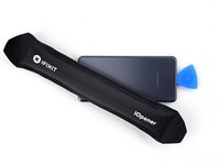
Heat an iOpener and apply it to the back cover's bottom edge for two minutes.
-
-
-
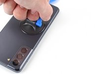
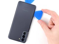
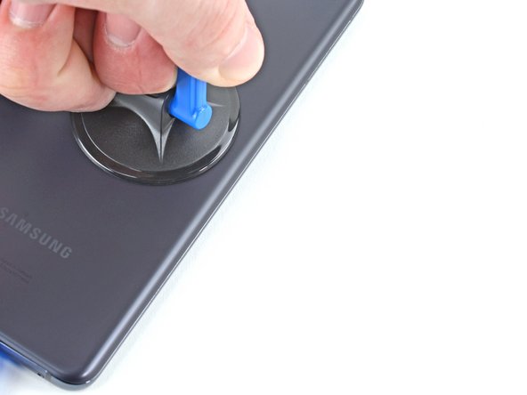
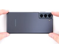
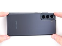
Apply a suction cup to the back of the phone, as close to the center of the bottom edge as possible.
-
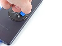
Pull up on the suction cup with strong, steady force to create a gap between the back cover and the frame.
-
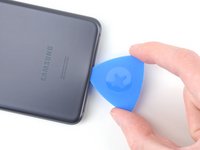
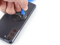
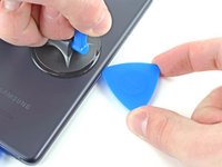
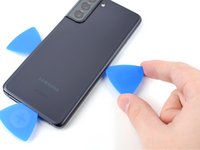
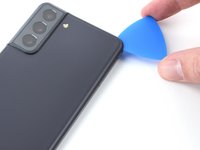
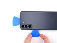
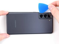
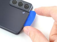
Insert an opening pick into the gap.
-
-
-
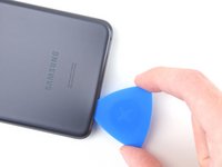
Slide the pick back and forth along the bottom edge to slice through the adhesive.
-
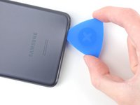
Leave the pick in to prevent the adhesive from resealing.
-
-
-
Apply a heated iOpener to the back cover's left edge for two minutes.
-
-
-
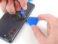
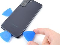
Apply a suction cup to the back of the phone, as close to the center of the left edge as possible.
-
Pull up on the suction cup with strong, steady force to create a gap between the back cover and the frame.
-
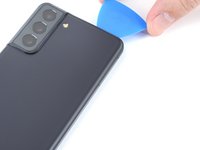
Insert an opening pick into the gap.
-
-
-
Apply a heated iOpener to the back cover's right edge for two minutes.
-
-
-
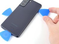
Apply a suction cup to the back of the phone, as close to the center of the right edge as possible.
-
Pull up on the suction cup with strong, steady force to create a gap between the back cover and the frame.
-
Insert an opening pick into the gap.
-
-
-
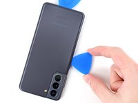
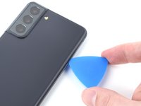
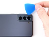
Rotate the right-edge opening pick around the top-right corner of the phone.
-
-
-
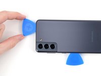
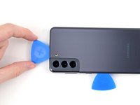
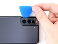
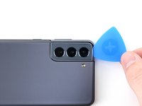
Slide the top-most opening pick as close to the camera shell as possible.
-
Repeat for the left-edge pick.
-
-
-
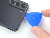
Heat an iOpener and apply it to the camera shell for two minutes.
-
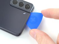
There's additional adhesive to the right of the camera that you need to cut through.
-
Angle the pick downward to avoid any damage.
-
-
-
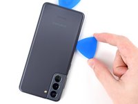
Rotate the back cover counterclockwise to create a gap between the camera shell and the frame.
-
Insert an opening pick in the gap.
-
-
Outil utilisé dans cette étape :Tweezers$4.99
-
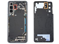
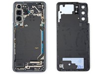
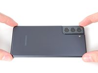
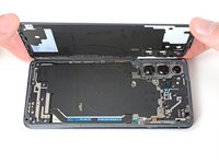
Remove the back cover.
-
This is a good point to power on your phone and test all functions before sealing it up. Be sure to power your phone back down completely before you continue working.
-
Remove any adhesive chunks with a pair of tweezers or your fingers. Apply heat if you're having trouble separating the adhesive.
-
If you're using custom-cut adhesives, follow this guide.
-
If you're using double-sided tape, follow this guide.
-
-
-
-
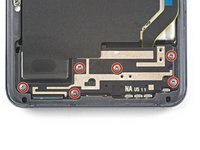
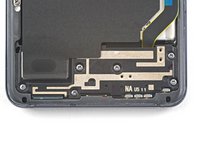
Use a Phillips screwdriver to remove the five 4 mm-long screws securing the motherboard bracket to the frame.
-
-
Outil utilisé dans cette étape :Tweezers$4.99
-
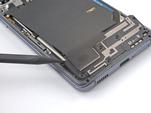
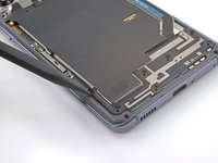
Use a pair of tweezers to gently pull up and unclip the motherboard bracket from the frame.
-
-
-
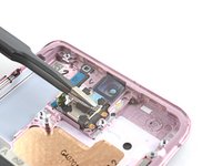
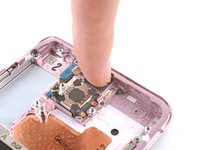
While using tweezers, or your fingers, to hold the motherboard bracket out of the way, use a spudger to pry up the battery press connector.
-
-
-
While holding the motherboard bracket out of the way, use a spudger to pry up and disconnect the wireless charging coil's press connector.
-
-
-
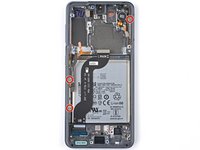
Use a Phillips screwdriver to remove the six 4 mm-long screws securing the loudspeaker to the frame.
-
-
-
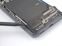
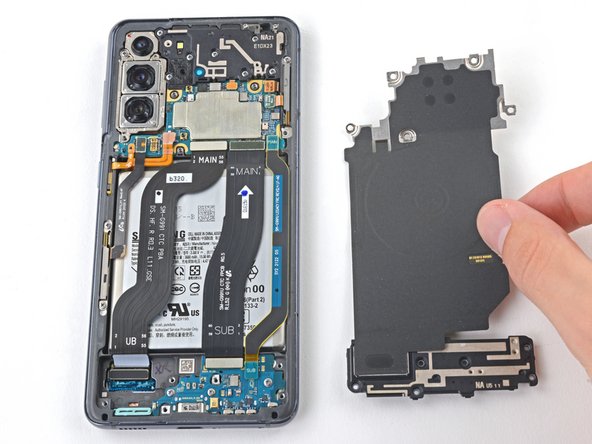
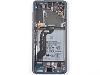
Insert the point of a spudger into the notch in the top-left corner of the loudspeaker and pry up to release the clips holding it in place.
-
-
-
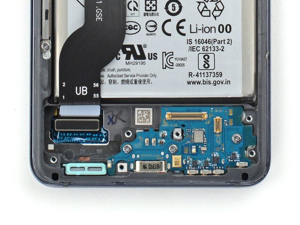
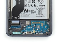
Use the flat end of a spudger to pry up and disconnect the primary interconnect cable's press connector.
-
-
-
Use the flat end of a spudger to pry up and disconnect the secondary interconnect cable's press connector.
-
-
-
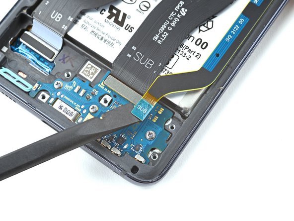
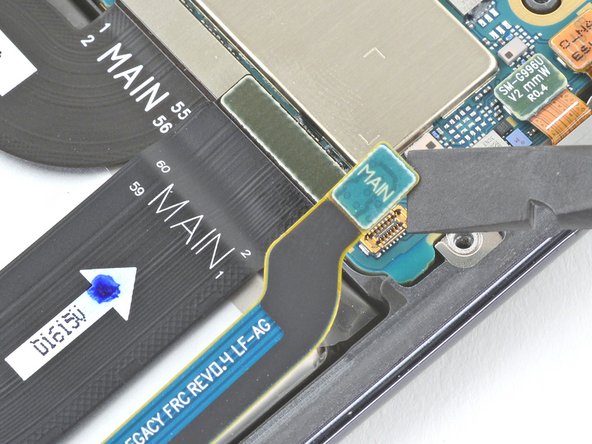
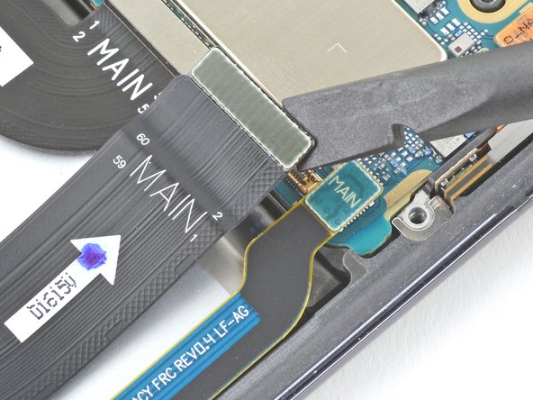
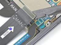
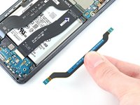
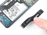
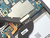
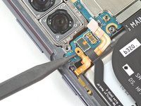
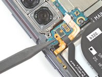
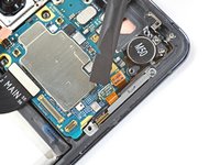
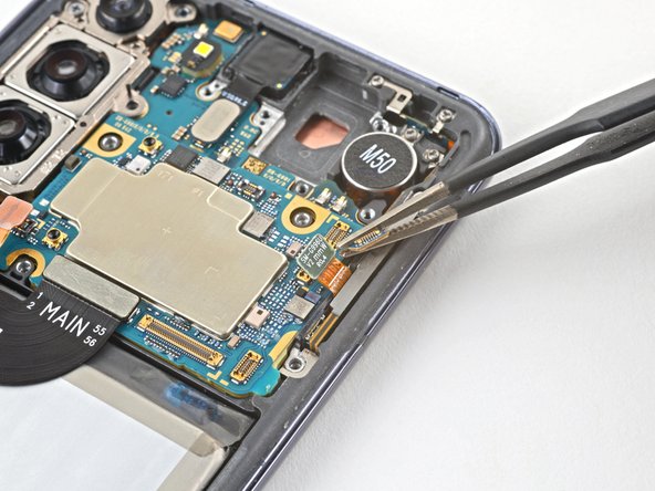
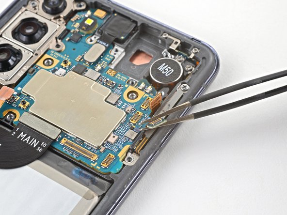
Use a spudger to pry up and disconnect the secondary interconnect cable's press connector.
-
Repeat for the main interconnect cable's press connector.
-
-
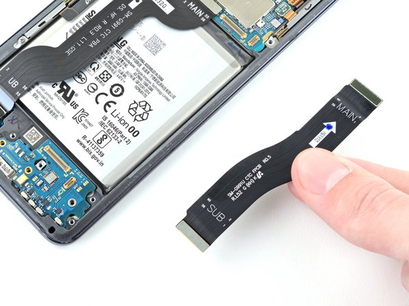
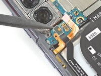
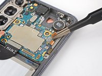
Outil utilisé dans cette étape :Tweezers$4.99
-
Use tweezers or your fingers to remove both cables.
-
-
-
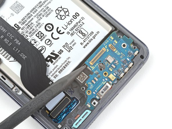
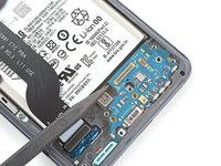
Use a Phillips screwdriver to remove the three 3.5 mm-long screws securing the daughterboard to the frame.
-
-
-
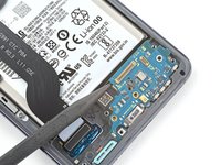
Use the point of a spudger to pry up the daughterboard.
-
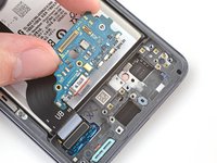
Use your fingers to pull the daughterboard up and away from the bottom of the phone and remove it.
-
-
-
Use the point of a spudger to pry up and disconnect the earpiece speaker cable's press connector.
-
-
Outil utilisé dans cette étape :Tweezers$4.99
-
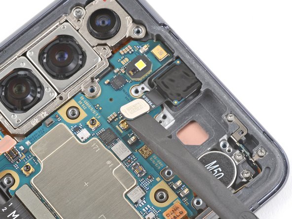
Insert the point of a spudger into the gap between the right-most edge of the earpiece speaker and the phone.
-
Use the spudger to pry up and release the clips holding the earpiece speaker in place.
-
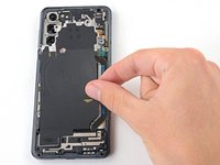
Use tweezers, or your fingers, to remove the earpiece speaker.
-
-
-
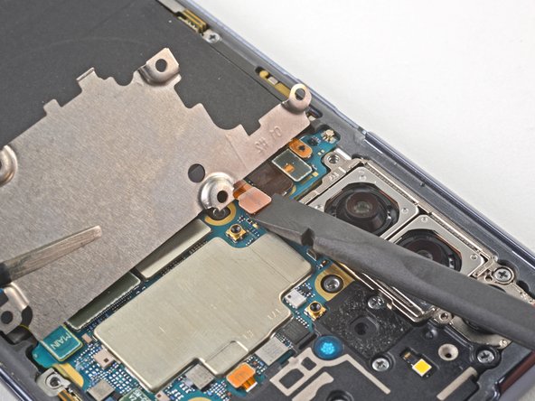
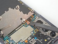
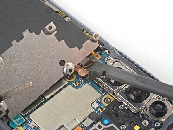
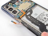
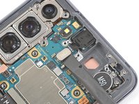
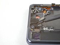
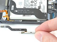
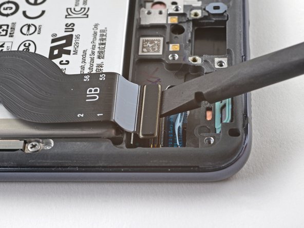
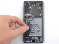
Use a spudger to pry up and disconnect the display cable's top press connector.
-
-
-
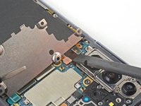
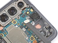
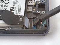
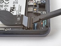
Use a spudger to pry up and disconnect the left 5G mmWave antenna cable's press connector.
-
Repeat for the power button cable's press connector.
-
-
-
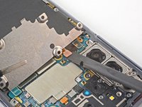
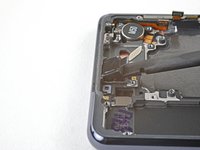
Use tweezers, or your fingers, to bend the power button cable away from the phone.
-
Repeat for the left-edge 5G mmWave antenna cable.
-
-
-
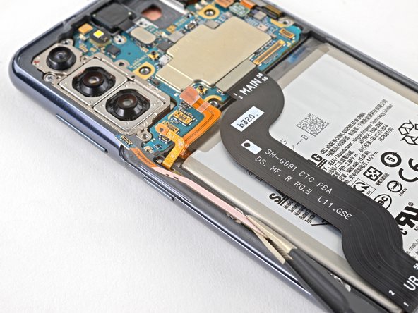
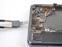
Use the flat end of a spudger to pry up and disconnect the front camera's press connector.
-
-
-
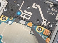
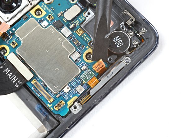
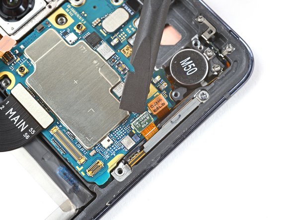
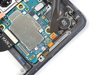
Use a spudger to pry up and disconnect the orange press connector adjacent to the 5G mmWave antenna cable's press connector.
-
Repeat for the green 5G mmWave antenna cable's press connector.
-
-
-
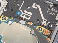
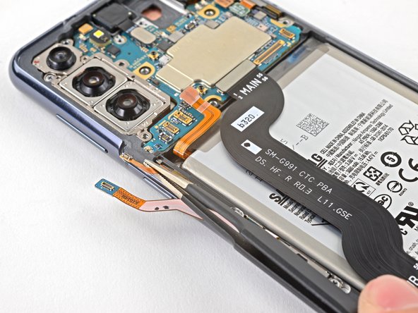
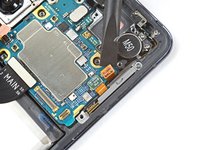
Use tweezers or your fingers to bend both right edge cables away from the motherboard.
-
-
-
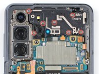
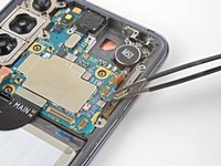
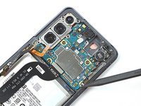
Use a Phillips screwdriver to remove the 4 mm-long screw securing the camera bracket and the motherboard to the frame.
-
-
-
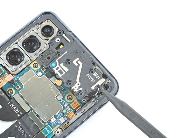
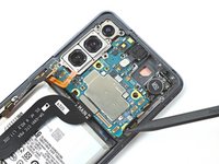
Insert a spudger between the bottom-right edge of the motherboard and the frame.
-
Pry up with the spudger to release the clips securing the motherboard.
-
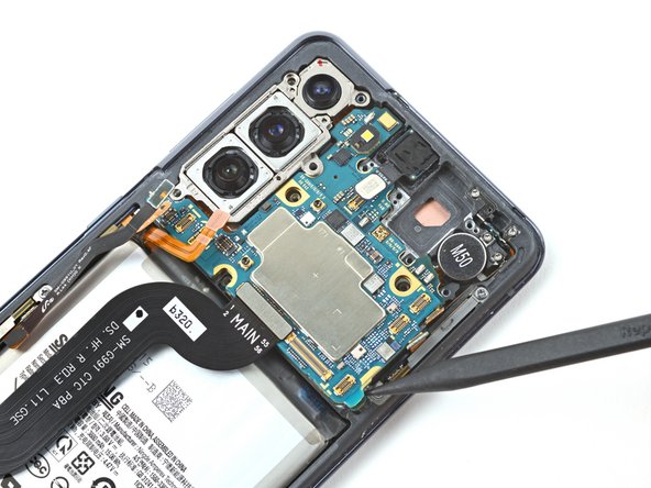
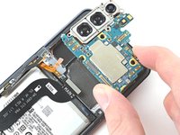
Use your fingers to remove the motherboard.
-
-
-
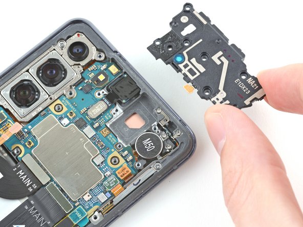
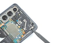
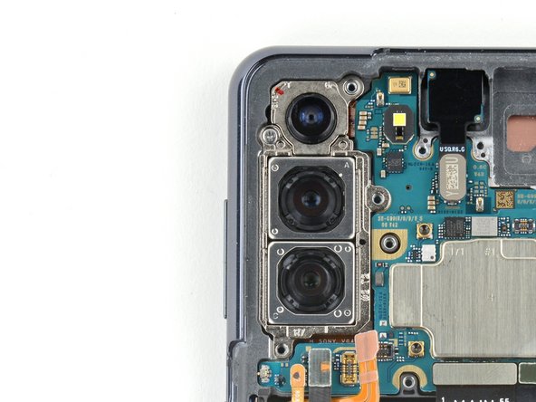
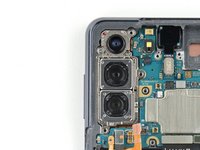
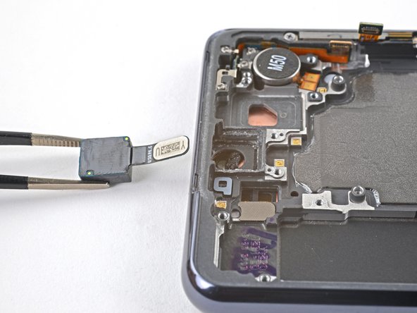
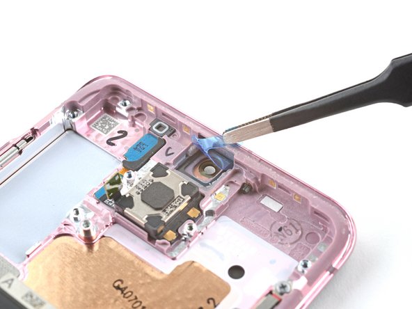
Insert the point of a spudger into the gap between the frame and the front camera.
-
Pry up with the spudger to detach the front camera.
-
Use tweezers, or your fingers, to remove the front camera.
-
-
-
Peel off the front camera adhesive from its liner and apply the sticky end to the frame.
-
Use tweezers, or your fingers, to pull on the tab and expose the top layer of adhesive.
-
Insert the front camera and apply pressure to adhere it to the frame.
-
-
-
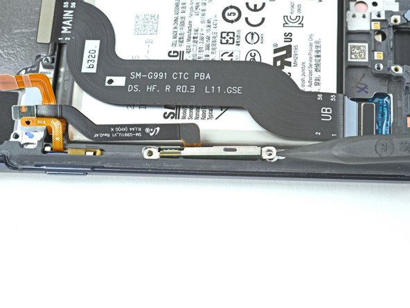
Use a Phillips screwdriver to remove the three 3.5 mm-long screws securing the 5G mmWave antenna brackets to the frame.
-
-
-
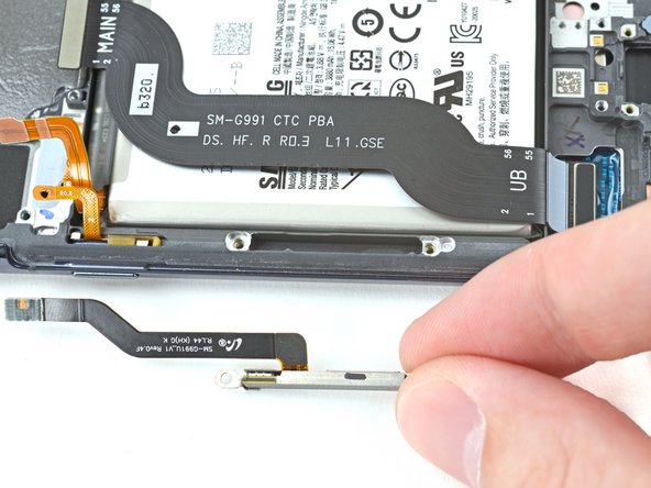
Use the point of a spudger to pry up on the right 5G mmWave antenna bracket's bottom screw tab.
-
Use tweezers, or your fingers, to remove the 5G mmWave antenna.
-
-
-
Use the point of a spudger to pry up on the left 5G mmWave antenna bracket's top edge.
-
Use tweezers, or your fingers, to remove the 5G mmWave antenna.
-
-
-
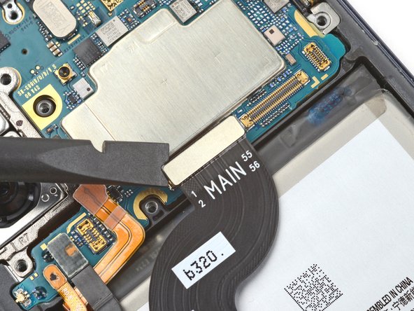
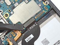
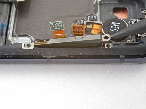
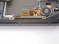
Use a spudger to pry up and disconnect the display cable's press connector near the bottom of the device.
-
-
-
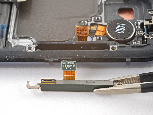
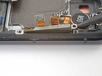
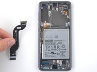
Use tweezers, or your fingers, to remove the display cable.
-
-
-
You're now left with the screen and battery assembly.
-


To reassemble your device, follow these instructions in reverse order.
Take your e-waste to an R2 or e-Stewards certified recycler.
Repair didn’t go as planned? Check out our Answers community for troubleshooting help.
To reassemble your device, follow these instructions in reverse order.
Take your e-waste to an R2 or e-Stewards certified recycler.
Repair didn’t go as planned? Check out our Answers community for troubleshooting help.
Annulation : je n'ai pas terminé ce tutoriel.
11 autres ont terminé cette réparation.


6 commentaires
As a note, you need to remove the flex antenna in the top right corner from the old frame and move it over to the new frame, or you won't have signal. This applies even if you have a antenna in the new frame. Takes a tri-point screwdriver bit.
Hi Vincent.
Thank you for your comment! The OEM replacement screen and battery assembly should come with the flex antenna pre-installed, and it should work properly after your repair. If your part didn't come with the antenna, please contact our customer support.
Seconded. I had no cellular after performing this repair, searching online I found dozens of reports of others with the same issue but no solutions.
I happened upon one mention of that antenna on a site and decided to transplanted, cellular function restored.
Came back here to comment my findings only to find that the information I needed had been here all along. D'oh.
Guide should really be updated to include this @alexdk
I had followed the steps and the phone is back up, however it keeps telling me now Incorrect pin even though I am putting in the correct one. Is there any I should double check is seated properly?