Introduction
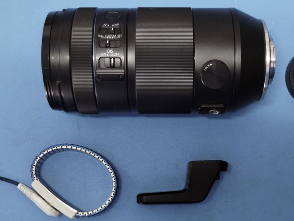
This Samsung NX 50-150 f/2.8 Lens has a fault where if the zoom is in a particular range the electronically controlled focus mechanism fails and the camera displays a message "Error 00" and turns off.
Initially I tried repairing the Flex PCB with some very fine (34AWG) stranded wire, but the required bend radius in the cable was too small and the solder links too fragile.
A replacement Flex PCB was then designed and manufactured. The design was to allow it to be spliced into the stubs of the flex pcb going to the focus motor and sensor, so that the calibrated section of lens didn't need to be opened. This was challenging to solder, but achievable.
The lens now focuses correctly and does not show the "Error 00" message. Alignment of the lens does not seem to have been affected.
Ce dont vous avez besoin
Vidéo d'introduction
-
-
Symptoms
-
When focussing the camera may shut off with 'Error 00' message.
-
In manual focus mode the focus can not be adjusted, but the iFn ring does still work (e.g. for changing aperture).
-
Focus only works at some zoom levels.
-
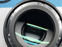
At a zoom level where focus does work, the focus elements can be seen to move through the front element.
-
-
-
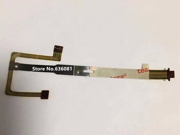
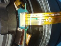
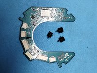
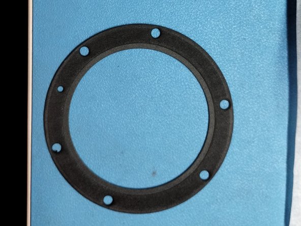
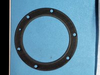
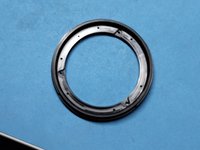
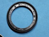
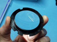
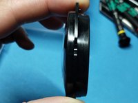
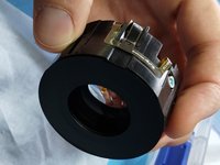
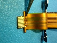
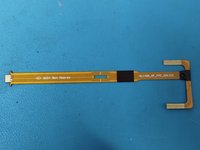
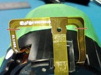
Some pictures of the FPC from when there was still some stock available to buy
-
-
-
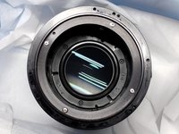
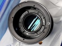
Detach lens from camera
-
Fit front cover to lens.
-
Fit sensor cover to camera.
-
Remove tripod attachment
-
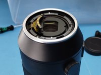
Prepare a clean (dust free) area with ESD protection.
-
-
-
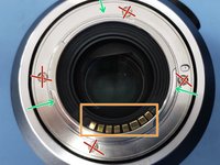
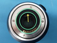
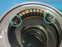
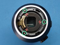
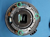
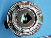
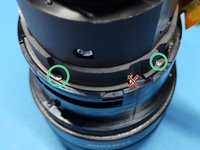
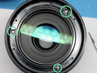
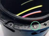
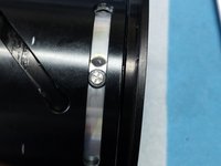
Using PH0 driver remove the 3 circumferential screws pointed to by the green arrows. Do not remove the 4 screws with the red crosses.
-
-
-
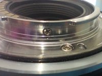
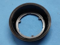
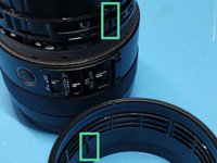
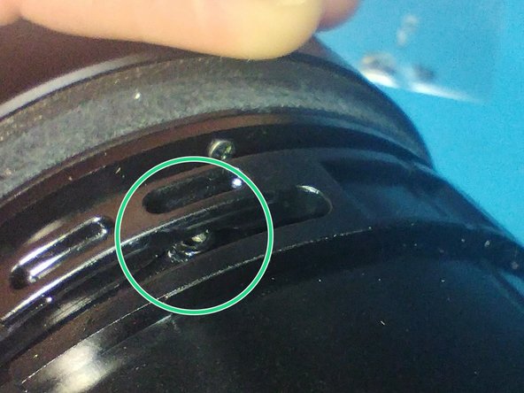
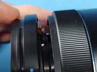
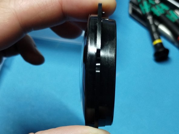
Using flat blade screw driver gently lift the retaining ring.
-
Work slowly and at multiple points around the circumference to lift the ring squarely.
-
-
-
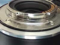
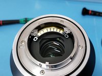
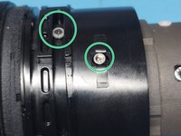
Using PH00 Screwdriver remove the two screws holding the contact block.
-
-
-
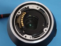
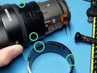
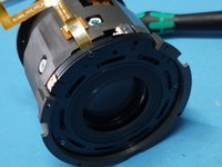
Using PH0 Screwdriver remove the 4 screws attaching the mount ring to the lens.
-
Carefully lift the mount ring. The lens sealing gasket may have adhered to it and lift as well. This is ok.
-
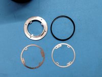
Remove the lens sealing gasket, and two metal shims.
-
-
-
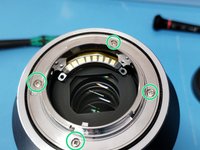
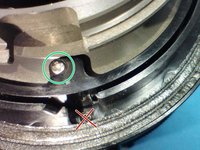
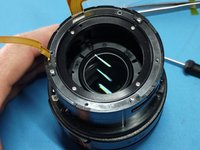
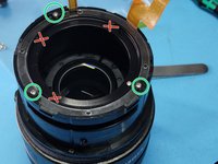
Using PH0 Screwdriver remove the three screws circled in green.
-
There is a rubber gasket under the conical section. Note the profile has the round surface fitting into the conical section, and the double wiper section pressing into the foam gasket on the body.
-
-
-
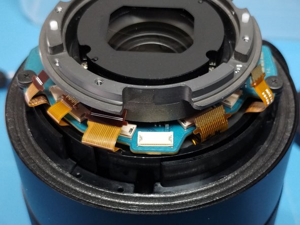
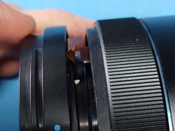
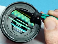
Insert the finest tip flat blade screwdriver between the tab on the ribbon cables and the white connectors, and gently pry the 6 FPCs out.
-
-
-
Using a PH0 Screwdriver unfasten the 3 screws holding the PCB. Turn each screw alternately a little at a time to avoid warping the PCB as it rises.
-
Note the 'C' shape of the PCB allows it to slide out horizontally. Take care to avoid catching the FPCs.
-
Place the PCB in an ESD safe bag
-
-
-
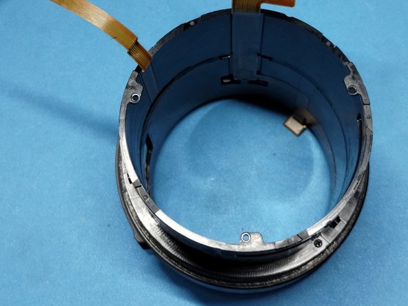
Using a PH0 Screwdriver remove the three silver screws in the middle ring of screws.
-
Lift the orientation ring. There are some felt pads on the lower lip that make it a little stiff, but it will lift out.
-
Screws: 3@ M1.6 x 4mm (white threadlock)
-
FPC Marking: XL1406_FPC_ENCODER_FPC_Rev03 UFK144513
-
-
-
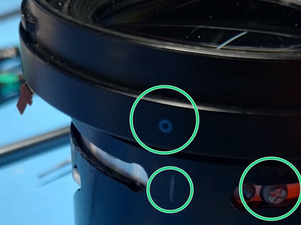
Using a PH0 Screwdriver (you may need to use a PH00 if the shaft is too thick to fit) remove the 3 deeply recessed screws in the zoom ring.
-
On this lens the rubber grip on the zoom ring was loose. Rotate the bodies zoom mechanism to the 50mm position (or 150mm), and then with the slots and ridges lined up, work out the correct position for the rubber grip by rotating it against the body. It appears to have been originally glued, but it can be repaired with some thin double sided tape.
-
-
-
Note that this lens has been apart once before. There was black tape securing the FPC ribbons which has been replaced with kapton (polyamide) tape.
-
The FPC Ribbons are double sided taped to the body
-
Note how the wide FPC ribbon that goes inside the metal body has been folded and taped together.
-
-
-
-
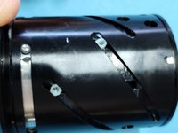
Remove the 3 screws and nylon bushes running in tracks around the zoom zoom ring mechanism.
-
Note how the nylon bushes sit over studs in the body.
-
Remove the recessed screw with the metal collar holding the zoom ring mechanism. This is the one that transfers torque to the internals.
-
Now that the plastic zoom ring is loose, rotate it until the metal studs on the body (that were holding the 3 screws and bushes) fit into gaps on the ring allowing it to be lifted off.
-
Screws: 3@ M1.6 x 3mm Wafer head (Black), + 1@ M1.6 x 4mm Wafer head (Silver)
-
-
-
Remove the black tape (in these pictures it has already been replaced by polyamide/kapton tape).
-
Gently unpeel the FPC ribbon cables from the body.
-
FPC Marking: XL1406_IRIS_FPC_Rev03 UFK144512
-
-
-
Using a PH0 ScrewDriver remove the 4 screws in the metal body (not the 3 screws in the plastic part)
-
Screws: 4@ M1.4 x 4mm Wafer head with threadlock
-
Lift the iris section off the body and place in clean box and seal.
-
-
-
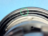
Using a PH0 Screwdriver remove the 3 silver screws holding the iFn sleeve onto the body. Do not separate yet.
-
Lie the lens on its side, and gently and gradually pull the front of the lens away from the body exposing a FPC Ribbon cable. Disconnect the cable from the connector and then finish separating the parts.
-
Screws: 3@ M1.4 x 4mm Wafer head (thread lock)
-
-
-
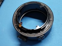
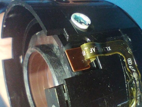
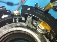
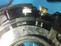
This shows the iFn ring and ribbon cables.
-
Note the quadrature encoders for the iFn ring.
-
The XL1406_MF_PI_FPC_Rev04 cable has the quadrature encoders, and also runs to the connector at the front which connects to the internal focus motor and presumably sensors.
-
The XL1406 Switch FPC Rev04 connects to the iFn button and selector switches.
-
-
-
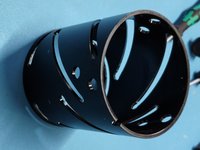
This shows the operation of the front section of the lens
-
The zoom functionality rotates the outer metal cylinder causing the inner sections to move within their races.
-
note the different angles of the slots causing the sections to move at different rates.
-
The focus mechanism sits inside this.
-
-
-
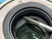
Insert a fine flat blade (screwdriver or knife) under the flat ring with the lens details printed on it.
-
carefully slide around the circumference to release the glue
-
From this point, use a pencil to mark on the plastic pieces how they are oriented relative to each other. Remember the outer barrel can rotate, so you need to remember if its rotated to its maximum extent clockwise or anticlockwise.
-
-
-
Use PH00 Screwdriver to remove the six screws holding the the seal cap.
-
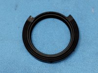
Lift the plastic ring, and the foam seal underneath.
-
-
-
Use PH00 Screwdriver to remove the 3 screws holding the bayonet ring (and filter holder)
-
-
-
Use PH0 driver to remove the 3 screws holding the front lens
-
Place the lens in a clean container to avoid contamination
-
-
-
At this point we are left with the inner interlocking barrels.
-
The cover for the focus mechanism FPCB is also visible
-
-
-
The rear end of the barrel assembly has a metal cap
-
Using PH00 Screwdriver remove the 4 screws
-
Use a flat blade screwdriver to carefully lift the cap at multiple points around the circumference. It is a tight fit.
-
Be careful when removing it, as there is a plastic spacer underneath.
-
-
-
Using a flat blade screwdriver remove the three special screws in the straight guides at the front of the lens.
-
Using a PH0 Screwdriver remove the 6 screws and spacers holding the two groups of lenses in place.
-
The outer barrel can now be removed.
-
-
-
Remove the two screws holding the focus cable guard
-
On the outside of the barrel you will see a small slot and a prong. This is the bottom end of the cable retainer.
-
Move the cable retainer inwards, there is a small amount of glue at the bottom that will separate.
-
The Focus group can now be removed
-
-
-
Some pictures of the focus element
-
Note the varnish / thread-lock on the screws inside the special white spacers. This is aligning the lenses.
-
The white spacers will be eccentric, so as they are rotated through 360 degrees (note the torx shaped inner wall), the lens will lift up or down, and then can be locked in place with the screw.
-
disassembling and reassembling this section will require marking each spacer exactly so that it can be put back in precisely the correct location.
-
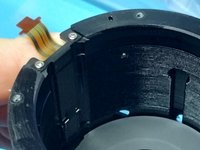
Note the optical proximity sensor which is detecting the inner mechanisms endpoint (towards the motor).
-
-
-
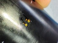
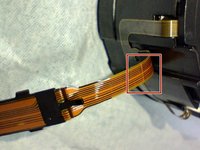
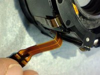
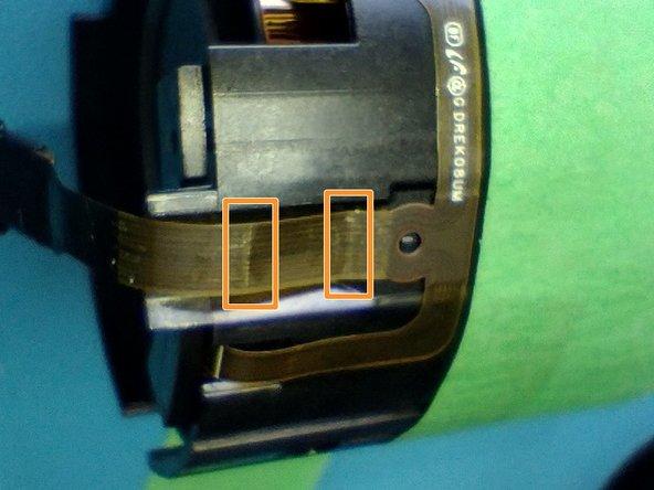
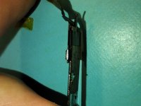
Inspecting the flex-pcb shows the likely fault. Over time the flex-pcb has developed a weak spot, which then becomes the point that flexes the most, causing it to weaken even further.
-
Flexing the cable shows that this spot is bending at a sharp angle.
-
-
-
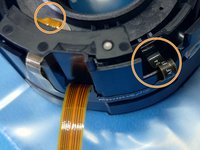
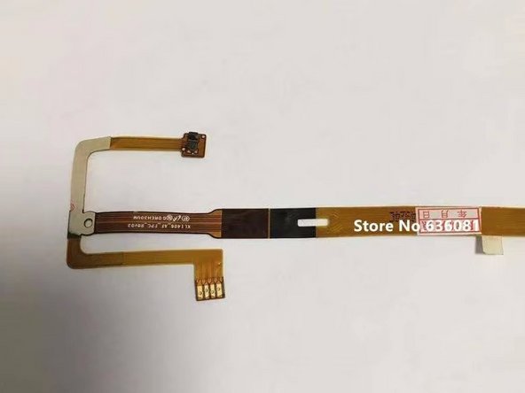
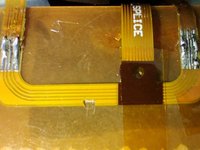
From the connector pinout we can follow the traces
-
Pin 1 (with white dot) - Pin 4 : These go to three traces in the flex PCB, and go towards the sensor. Pins 2 and 3 are joined.
-
Pins 5-8 : These go to the stepper motor. Pins 5 and 7 appear to be one winding, and pins 6 and 8 the other winding.
-
The wider copper strips on the outside and middle are not connected.
-
Flex ribbon details:
-
0.07mm thick. There is at least 1mm gap between the focus elements and the inner barrel wall.
-
Stiffener thickness (at end with gold fingers) 0.30mm
-
As there are two weak spots (orange boxes) in the cable, the repair needs to run from before the first to after the second.
-
-
-
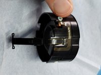
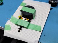
Use masking tape to hold things in place while you work on them. I also cut some pieces of rigid foam to hold things in position. I recommend mounting this on a board that you can rotate for soldering at convenient angles. Cover the lenses (I used pieces of ziplock bag taped across) to avoid flux splash or dust while working.
-
Use a scalpel to scrape away some of the epoxy coating, being careful not to cut the copper traces.
-
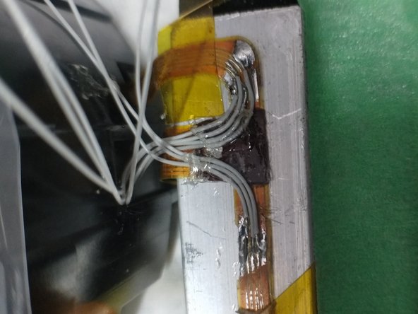
Use some 34AWG stranded wire to replace the damaged section to flex PCB.
-
Use a multimeter to check the best you can, as you don't want to have to disassemble it again after testing.
-
Clean with flux remover on cotton swabs. Followed by IPA. Insulate with kapton/polyamide tape. Use double sided tape to reattach cables where they need to go.
-
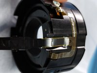
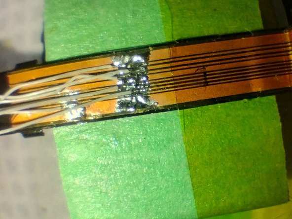
Soldering the ribbon was very difficult. The traces were ~0.1 - 0.2mm wide. Stagger the soldering positions to help avoid shorts. At this stage I'm giving this repair job a 20% chance of success. If this doesn't work I will manufacturing a new flex ribbon - although I fitting to the motor will be challenging without removing the calibration screws.
-
-
-
After the initial failed repair attempt using thin wire, a Flex PCB was designed to splice into the stubs of the original flex PCB going to the motor and sensor.
-
JLCPCB.com was used to make the cables, but other suppliers could be used. The second picture shows the manufacturing details.
-
See https://github.com/mostlyhorses/XL1406_A... for the PCB gerber files
-
-
-
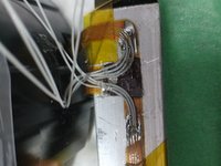
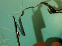
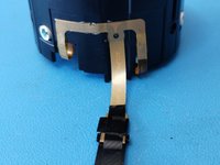
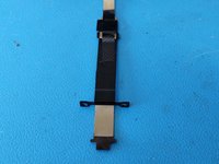
Cut the original flex PCB from the focus mechanism (red lines in first picture), leaving a tail from the motor and sensor for splicing onto replacement cable.
-
Notice how the flex PCB is adhered and folded into the metal carrier, including how the tape has been placed.
-
-
-
Scrape the coverlay off the original flex pcb so that it can be soldered to. Be careful not to damage the traces as you don't have much to work with.
-
Join the new flex pcb to the stubs. This was more difficult than I hoped, as the solder would not bridge across the 0.07mm height difference reliably. The technique I used was
-
Use the double sided tape to attach the stub to the long tail of the splice PCB.
-
Use a much cooler soldering iron than usual, so that the solder can be 'moulded' as you push it around with the iron tip. If you get the right temperature it will be much easier.
-
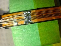
Bridge the outer traces and the guard sections of PCB so you can use a large blob of solder here, which will bridge the gap between the two PCBs. Note how I've cut a piece out of the guard section so it doesn't join the motor and sensor.
-
On the inner traces use a fine strand of wire to join the sections.
-
Insulate the soldering with polyamide tape and reattach it to the body using double sided tape.
-
Check with a multimeter that the traces are connected and not shorting. Note that Pins 5 and 7 are one motor winding, and pins 6 and 8 the other, so they will measure as connected, but as they have a trace between them you can tell it's intentional and not a soldering short.
-
-
-
Use the Helimax-XP grease to lubricate the barrels and other rotating parts. I didn't apply enough, but I don't want to open the lens again to add more.
-
When re-installing screws into plastic, gently turn them backwards (anti-clockwise) until you feel the thread engage before tightening them clockwise.
-
Don't overtighten the screws
-
-
-
Take some test picture at different focal lengths to check auto-focus works and that nothing is out of alignment.
-


To reassemble your device, follow these instructions in reverse order.
To reassemble your device, follow these instructions in reverse order.