Ce dont vous avez besoin
-
-
You may need to reapply heat repeatedly throughout this process to prevent the adhesive from cooling and hardening.
-
Prepare an iOpener and place it on the bottom edge of the iPad's screen for about two minutes.
-
-
-
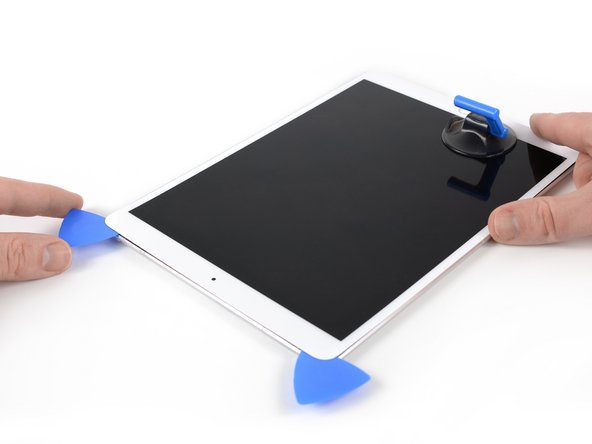
Place a suction cup next to the iPad's home button and press down to create a seal.
-
Firmly pull up on the suction cup to create a small gap between the front panel and the rear case.
-
Once you've opened a sufficient gap, insert an opening pick into the gap.
i used a proper suction tile puller (small one from DIY store used to hold bathroom tiles) to lift the screen off after heating around the edge using a heat gun. Be careful - It didn't damage anything. The tiny suction things that come with those iPhone kits are not strong enough for this. The one in picture might be good, but looks similar to the kits ones that have key ring.
The suction cup that comes with the iPad battery replacement is plenty large enough and strong enough.
CAUTION, do not push the picks in more than a the width of the replacement screen adhesive strips. You will damage the $200 screen, maybe break the glass. The screen is multiple layers and the picks can get in-between the layers if you push too far in. I got into trouble at the lower left corner. After getting the screen loose, I found that I only need a 2-3 millimeters on the sides and bottom, and four or five millimeters in the corners.
-
-
-
Slice through the adhesive under the screen by sliding the pick along the edge of the display, towards the bottom left corner.
-
Leave the pick in place temporarily to prevent the adhesive from re-sealing.
-
-
-
Apply heat to the left edge of the iPad for about two minutes, or until it's slightly too hot to touch comfortably.
-
If necessary, re-heat your iOpener for a few seconds or until it's a bit too hot to touch. Be careful not to overheat the iOpener, or it may burst.
-
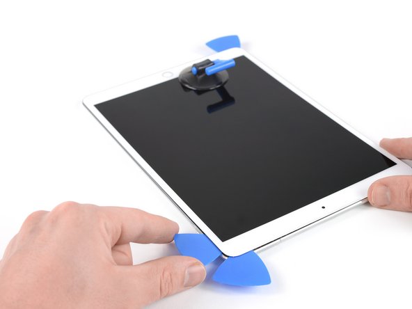
Insert a second opening pick at the bottom left corner of the iPad.
-
Slide the second opening pick along the left side of the display to separate the adhesive underneath.
-
Leave the opening pick inserted near the top left corner of the iPad to prevent the adhesive from re-sealing.
-
-
-
Apply heat to the final, right edge of the iPad for about two minutes, or until it's slightly too hot to touch comfortably.
-
Insert a fourth opening pick at the top right corner of the iPad.
-
Slide the opening pick down to the bottom right corner to cut the adhesive.
-
Slide the opening pick around the bottom right corner—pausing to apply more heat if needed—and cut the remaining adhesive on the bottom edge, but stop before you reach the home button.
We must be very careful when we are prying left and right size bezel to peel off the screen as there very little gap between edges and LCD. Slightly inside push can crack LCD. We need to pay full care and raising edges very very slowly.
-
-
-
Insert a fifth opening pick at the top of the iPad near (but not directly on) the front-facing camera.
-
Gently twist the pick to separate the display assembly from the iPad.
-
If needed, apply more heat and/or cut any remaining adhesive that prevents the display from separating.
Be very gentle when twisting. My screen broke in this step. I would not twist it but try to remove glue further as there is a aluminium support of the screen in the wide area beneath the light sensors and there is glue on that also preventing in easy lifting the screen. Just be careful not to damage the light sensors and camera.
-
-
-
Lift the display assembly from its top edge and carefully slide it up (towards the front-facing camera and headphone jack), until the screw that secures the battery power connector is revealed at the bottom.
How do you go about getting to this battery connector as it is covered by a large metal shield above the logic board, if you do not disconnect the battery you risk frying the back light.
The metal shield is not relevant for this. You can leave it in place or remove it if it comes of. Once the screw of the plate is removed you will be able to lift the print a little bit and put someting between the battery connector and the board connector. The connector is beneath the print. Look further on to see a deck card is used for this.
-
-
-
This picture looks nothing like my A2152 battery connector. I can’t really tell what is happening here.
-
-
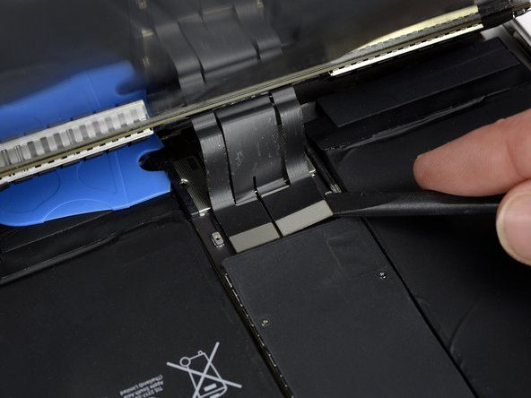
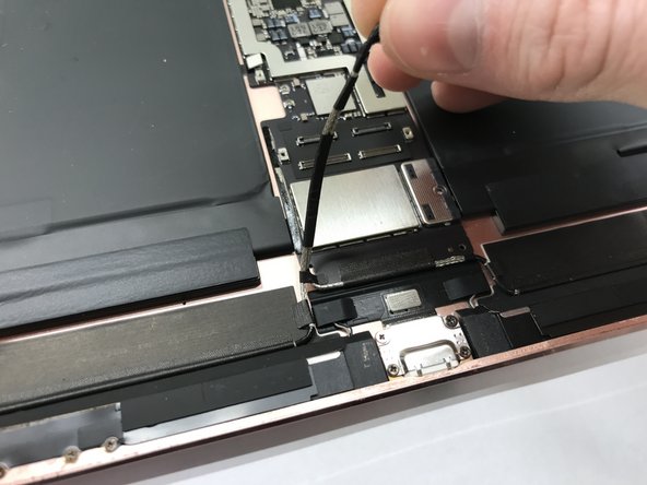
To disconnect the battery, slide one prong of a battery blocker or the tip of an opening pick under the battery power connector to ensure the power circuit is interrupted.
-
Leave the battery blocker in place as you work.
I found it very hard to fit something under the battery power connector. I did not have a battery blocker, so I tried a playing card. I was not able to slide it between the springs. The section of the battery power connector, above the cantilever springs, did not seem to want to give at all, like in the picture above. If other people had success, I would love to hear how.
I didn’t have success either, but i kept myself grounded, and avoided battery contact as much as possible.
I used a playing card cut to shape. I had to make a couple, to try a few times.. It does go in eventually. Not deep, but enough to break connection. You can test by trying to switch on iPad.
It took some time but I was able to get it under the back part and slide it forward.
You must disconnect the battery before plugging the new screen. I think i didn't break the circuit in first attempt and shorted the screen, the result was half of the screen didn't work. I used a playing card. Second attempt was successful with new screen.
I believe I have a good solution to this problem. I was dissatisfied with the thickness of the battery blocker, or even a thin guitar pick, for that matter; both required force and I feared bending the springs or leaving the connection intact.
What worked for me was cutting a small strip of non-conductive, static-proof film (the kind that RAM and other sensitive components come in). There was every reason to trust in its non-conductivity but just to be sure, I used a VOM to test; its resistance was out of the VOMs range, meaning that its conductivity was nil. I used a spudger to gently lift the logic board off of the battery contacts and slid the non-conductive strip in between; went without a hitch.
When reassembling, I laid the strip on the battery contacts, laid the logic board on top, installed it, connected the display panel and gently drew the slip out and installed the battery screw. Worked like a charm.
These are some extremely misleading set of instructions and picture. Much better if you have the battery discharged, so don't need to worry about blocking the connector. But DO NOT force anything in the through the socket and certainly do not try to bend up the soldered cover, as it appears to be happening in the picture. You will break the connector, most likely resulting in ipad shutting down every 3 minutes from the notorious "thermal sensor missing" panic system crash.
-
-
-
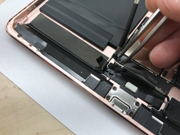
Slowly lift the display from its top edge, being careful not to strain the attached ribbon cables.
-
Remove the two 1.3 mm Phillips screws securing the display connector cover bracket.
-
Remove the display connector cover bracket.
Here it is very precocious steps to do. Flx cables to connectors are small in size and we cannot lift the display vertically. Therefore, we may struggle to unscrew the metal shield. We need to use smaller size of philip screw driver or place vertically the display to create enough gap between philip screw driver and the cover bracket. Similarly, when we are replacing new display we need to be carefully connect four flex cable with connectors with logic board.
agree, with re-assembly very tiny screws and awkward positioning, the back two cables pop off if not careful.
I did this step using just the tip of the PH000 screwdriver, it made it much easier to get my hands into the small space, the replacement screen from ifixit had tighter cables that I was not comfortable stretching out to go to a 90* angle to screw back on. Make sure your tip is magnetized for best results :)!
Meaning no disrespect for this excellent guide, I found this photo to be a bit misleading; at least in my case. It clearly shows about 90˚ between the case and the display. I tested the limits with the one I was repairing and could find no way to raise the display far enough to clear a screwdriver without jeopardizing the cables. I resorted to the same solution that Amber Wooldridge discovered; using a PH000 bit and hand-tightening. I had a tiny needle-nosed plier that I used to tighten them a bit (but very gently).
-
-
-
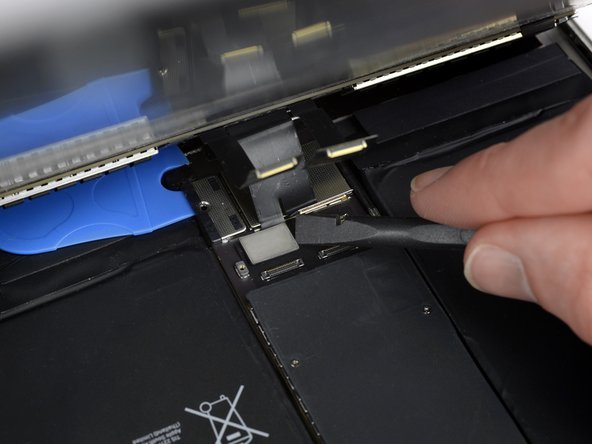
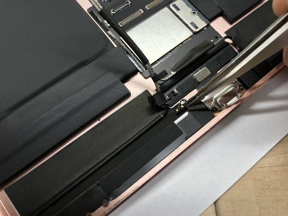
Use your spudger to gently pry them up and disconnect them.
I went to replace the LCD assembly on an ipad Air 3, and one of the flex cables on the new LCD assembly broke in half. The flex cables on the old assembly work well and are intact. Is it possible to transfer the old flex cable(s) to the new assembly, or can I solder the broken pieces of the new flex cable together? I have also contacted the part supplier about this and am awaiting a response.
-
-
-
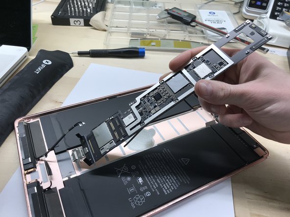
Remove the display assembly.
Definitely test your iPad’s functions before sealing it up. I needed to reopen the display to reconnect the display connectors in order to have the display functioning properly. As a result, the adhesive strips did not work as well and I needed to tape some of the edges closed with a small section of strong clear packing tape.
I stuck the adhesive to the chassis first. That was messy because the plastic that covers the adhesive seems to be for screen side first. So you end up exposing both sides and those collect dust. I now realise you're supposed to put the adhesive on screen first. Not sure if it would have made much difference in the outcome (mine screen is not stuck in some places).
I found this out too. I had two sealing kits and they were both meant to be fixed on the screen first. I did not managed to get the screen to stick with the body as well. Now used some B6000 glue in addition.
agrior -
-
-
-
Remove the following 10 Phillips #000 screws.
-
Eight 1.3 mm screws
-
Two 2.3 mm screws
-
-
-
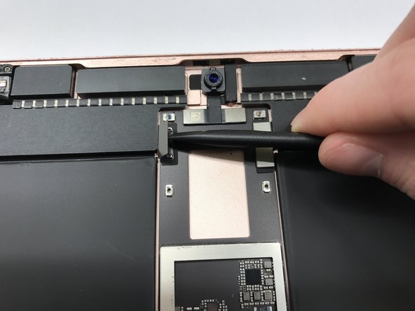
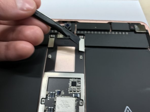
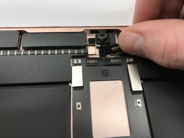
Disconnect the front camera FPC's.
-
-
-
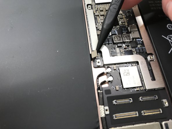
Gently pull up on the antenna coax cable to separate it from the logic board.
You give no indication of the cover or the purpose of the ports below the antenna
I’m slightly confused by your comment. The scope of this guide is to remove the main logic board from the housing of the iPad. Replacing the antennas is out of the scope of this guide. (please feel free to use this guide as a starting off point to create a new guide.) If you are referring to the lightning flex cable, please view step 24 and 26 to safely remove the charge port which is attached to the main logic board. As far the purpose for a particular part/port, you will need to contact Apple (best of luck to you on that hihi). I didn’t design the device.
-
-
-
Remove the following Phillips #000 screws.
-
Two 2.4 mm screws
-
Two 1.7 mm screws
-


To reassemble your device, follow these instructions in reverse order.
To reassemble your device, follow these instructions in reverse order.
Annulation : je n'ai pas terminé ce tutoriel.
11 autres ont terminé cette réparation.

Équipe

3 commentaires
Just wanted to share that an easier route is to use an eBay iPad logic board service. You mail your iPad in and they fix and return ship. I have availed services from two sellers for my iPad pro 10.5, once to replace the charging port and a second time when something shorted out on the logic board. Local repair shops can plug in a little tester into the lightening port to test whether it’s a broken connector, burned out tristar power IC or something else shorted out. Depending on where you live, it may be cheaper to just mail in to eBay sellers. Depending on the issue, it can be around ~$100 total to just replace a connector or shorted component, including mailing costs.
Can you replace the logic board w/an (upgrade)A12 chip logic board?
Im broke musician desperate for midi functions & logic plz and ThaNk yOu
🙏